

Thermal lump and its application in combustion chamber
A heat insulation block and combustion chamber technology, applied in the direction of combustion chambers, continuous combustion chambers, combustion methods, etc., can solve problems such as adverse force input, achieve the effects of increasing passive safety, extending inspection and maintenance intervals, and avoiding subsequent damage
- Summary
- Abstract
- Description
- Claims
- Application Information
AI Technical Summary
Problems solved by technology
Method used
Image

Examples
Embodiment Construction
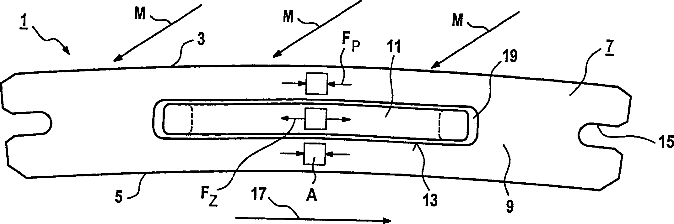
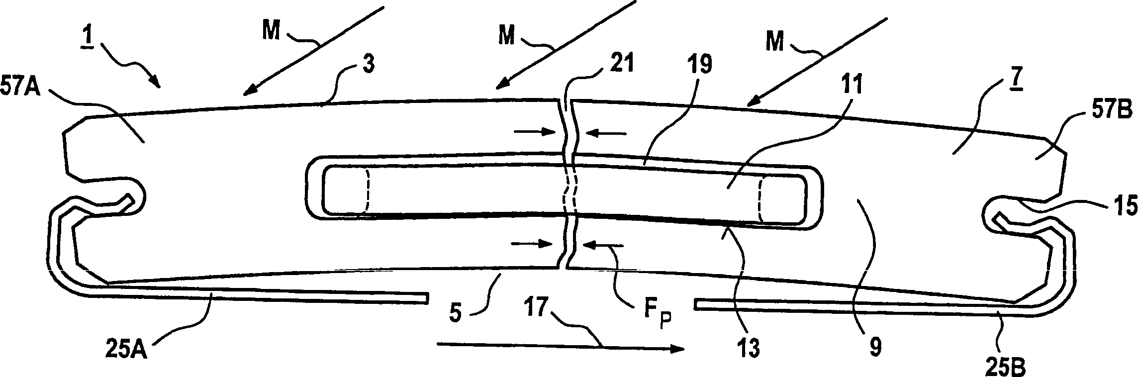
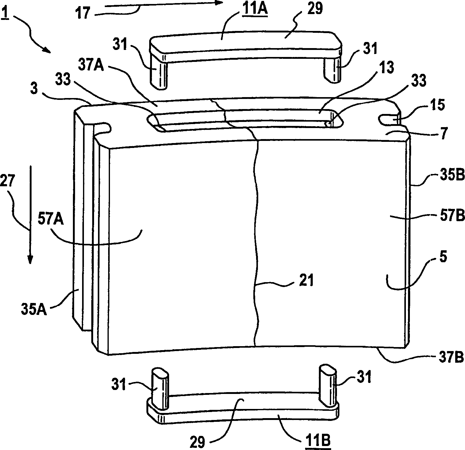
[0043] figure 1 The insulating block 1 is shown in side view. The insulating block 1 has a hot side 3 and a wall side 5 opposite the hot side 3 . The peripheral side 7 of the insulating block 1 connects the hot side 3 and the wall side 5 . The peripheral side 7 has a peripheral side surface 9 . A thermal medium M (eg hot gas) acts on the hot side 3 during use of the insulating block 1 . The tensile element 11 , which is prestressed in the peripheral direction 17 , is arranged on the peripheral side 7 of the insulating block 1 . In this case the tensile element 11 is prestressed to the prestress F Z . The peripheral side 7 has a peripheral groove 13 in which the tensile element 11 engages. Due to the prestress F of the tensile member 11 Z , generating compressive stress F on the material of the insulation block 1 P , the compressive stress F P (for example) acting on surface element A. In this case, the tensile member 11 is pre-stressed to: compressive stress F Z The...
PUM
 Abstract
Description
Claims
Application Information