
Motion sensor data processing and interface and method thereof

Active Publication Date: 2010-03-04
HARMAN PROFESSIONAL INC
View PDF7 Cites 23 Cited by
  • Summary
  • Abstract
  • Description
  • Claims
  • Application Information

AI Technical Summary

Benefits of technology

[0004]The present invention addresses these and other problems by allowing a user to easily determine if a motion sensor is operational by observing a level indicator while “moving” in front of a panel of the motion sensor.

Problems solved by technology

However, problems exist in motion sensors in determining whether a motion sensor is in operation, and in detecting different levels of motion.

Method used


Image

  • Motion sensor data processing and interface and method thereof
  • Motion sensor data processing and interface and method thereof
  • Motion sensor data processing and interface and method thereof

Examples


Embodiment Construction

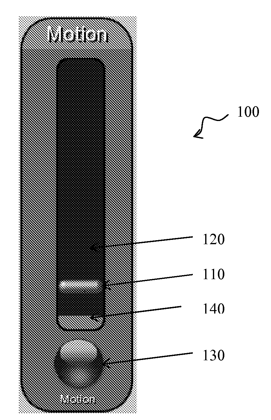
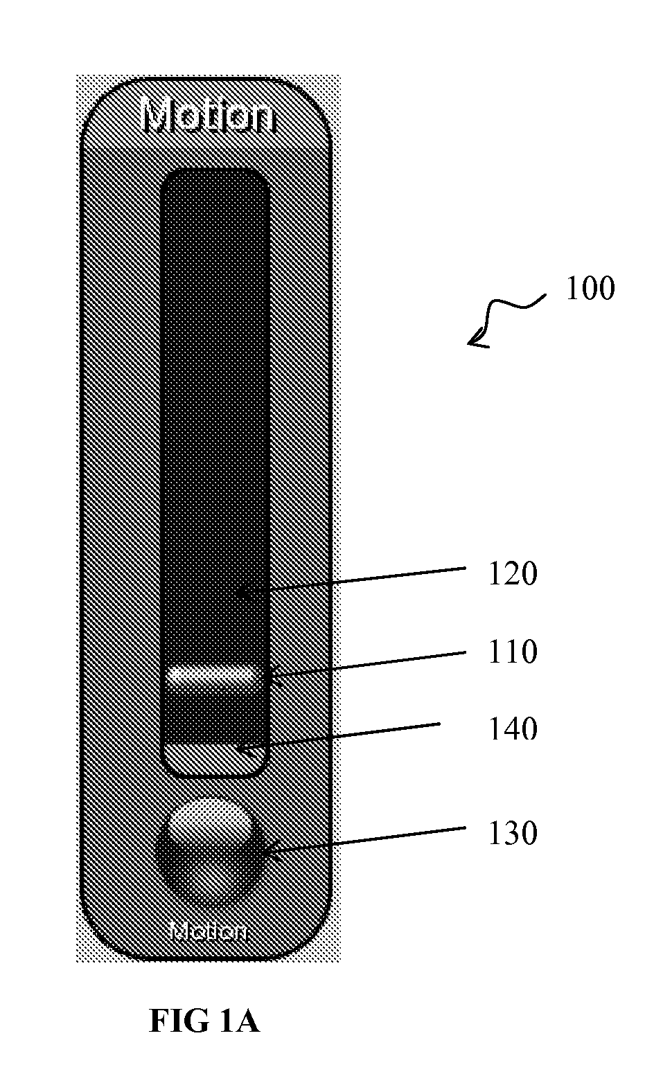
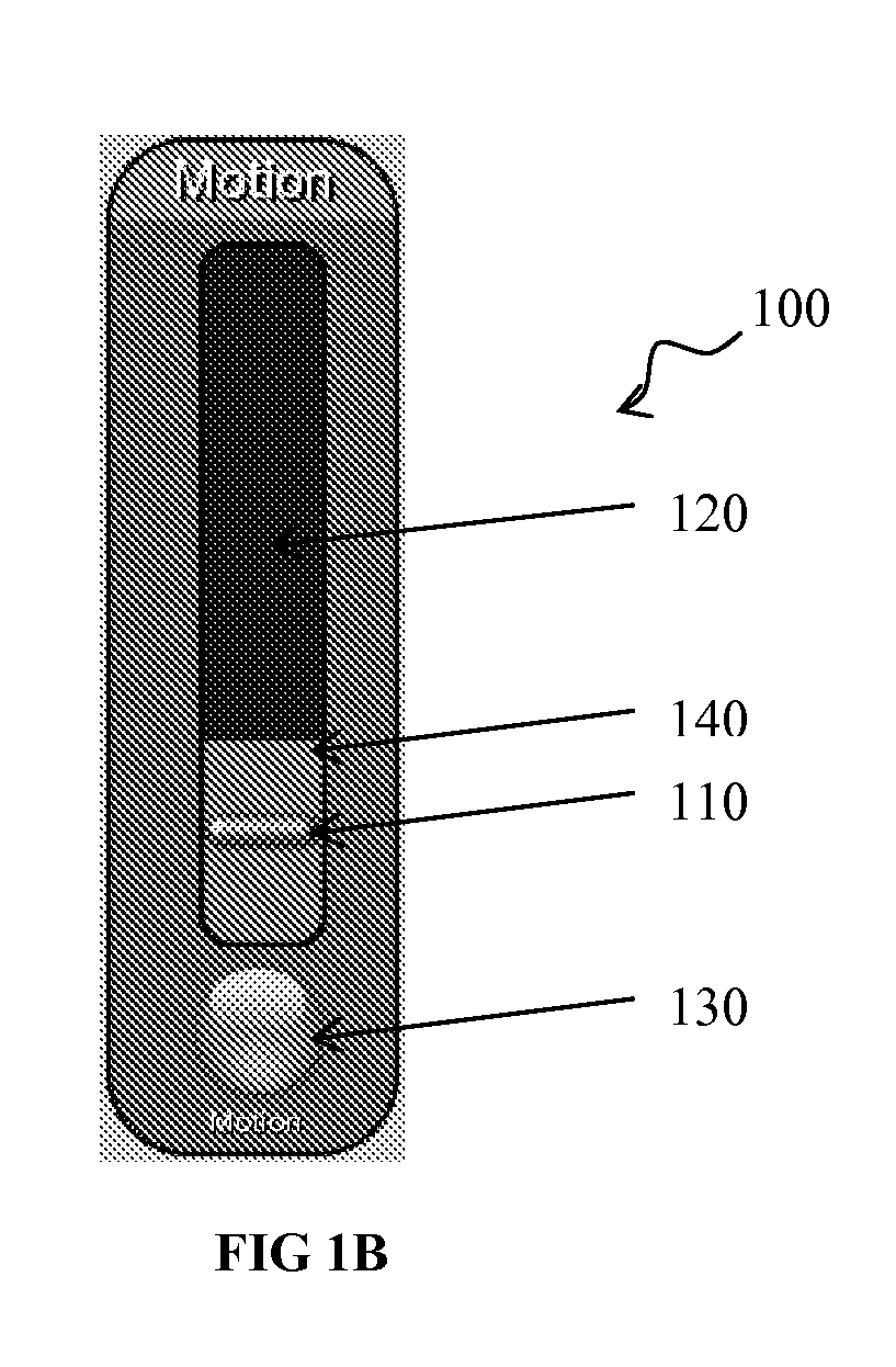
[0011]FIGS. 1A and 1B depict a motion sensor 100 of the present invention that is structured to sense lateral motion across the front of the motion sensor 100. The motion sensor 100 may be an independent element that can be affixed to a wall or other structure or may be integrated in another fixed element (such as a touch pad or other wall mounting) or to a mobile element (such as a touch pad, remote control, cellular phone, or other wireless apparatus). In FIGS. 1A and 1B, the use of the same reference numbers indicates similar or identical items.

[0012]In the invention, data from the motion sensor 100 may be processed using statistical methods. For example, a statistical mean may be calculated using 10 samples from the sensor. At 1 sample every 100 milliseconds, this represents 1 second in time. A variance may then be calculated to and / or from the mean to determine the “spread” of the data. As each new sample is acquired from the sensor, a new mean and variance may be calculated an...


PUM


Abstract

A motion sensor comprises a touch screen, and a motion indictor proximate to the touch screen, the touch screen displaying: an adjusting bar indicating a threshold at which motion is detected, and a level bar indicating an amount of currently measured motion.

Description

CROSS-REFERENCE TO RELATED APPLICATION[0001]The present invention is related to and claims priority from provisional patent application No. 61 / 087,048, filed on Aug. 07, 2008, the entire contents of which are incorporated by reference herein.FIELD OF THE INVENTION[0002]Apparatus and methods consistent with the present invention relate to motion detection. More particularly, the present invention relates to a motion sensor and method thereof that senses motion across the front of the sensor, and wherein data from the motion sensor is processed using statistical methods.BACKGROUND OF THE INVENTION[0003]Motion is typically detected by measuring a change in speed or vector of an object in a field of view. Motion detectors as in the present invention detect motion by quantifying and measuring changes in a given environment through, for example, optical detection and / or acoustical detection. However, problems exist in motion sensors in determining whether a motion sensor is in operation, ...

Claims


Application Information

Patent Timeline
IPC IPC(8): G06F3/041G06F3/048
CPCG06F3/04883G06F3/0485G06F3/0416
Inventor GELLING, RICHARD R.SMITH, GEORGE C.SHEEHAN, MICHAEL B.
Owner HARMAN PROFESSIONAL INC
Learn More