

Image input device
- Summary
- Abstract
- Description
- Claims
- Application Information
AI Technical Summary
Benefits of technology
Problems solved by technology
Method used
Image

Examples
first embodiment
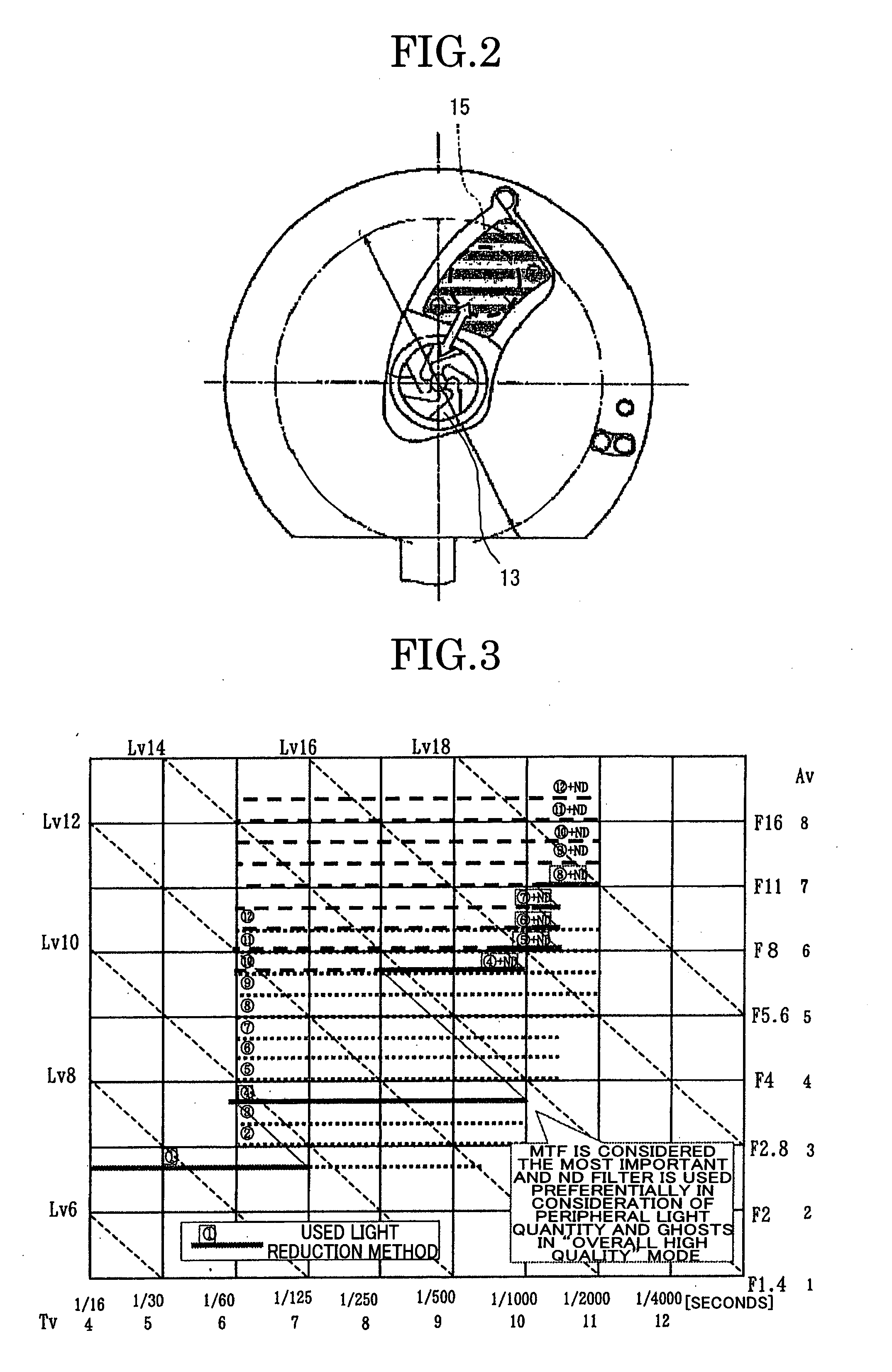
[0064]A description will now be given of control for a normal object in an overall image quality priority mode, which is the image input device according to the present invention, namely normal control in the overall image quality priority mode, with reference to an exposure chart shown in FIG. 3. An optimal high quality image is to be acquired in consideration of ghosts and a quantity of light on periphery in addition to the image forming capability (MTF) shown in FIG. 11 in this overall image quality priority mode, and the overall image quality priority mode in the normal state shown in FIG. 3 is a case where an extremely high luminance portion such as the sun, which causes ghosts, is not present on the screen of the object image. As described with reference to FIG. 11, if the aperture of the multistage aperture 13 is reduced to reduce the aperture diameter, though the resolution, which determines the image forming capability, decreases, the image forming capability does not large...
second embodiment
[0083]First, a description will be given of control for a normal object in the automatic mode, which is the image input device according to the present invention, namely normal control in the automatic mode, with reference to the exposure chart shown in FIG. 5. The control in the normal state whose exposure chart is shown in FIG. 5 carries out setting to acquire a proper image quality while considering the power consumption. Also in the exposure chart shown in FIG. 5, the horizontal axis represents the shutter speed and a TV corresponding thereto, and the vertical axis represents the aperture value by the first light reduction means, and an AV corresponding thereto. Circled numbers represent respective stages of the aperture adjustment for the adjustment of the quantity of light, and the light quantity can be adjusted in a ⅓-AV or ⅓-LV increment. Bold lines parallel with the horizontal axis indicate a program of a used light reduction.
[0084]The exposure control is carried out from a...
PUM
 Abstract
Description
Claims
Application Information