Spraying tool with a switch-off valve

Inactive Publication Date: 2010-06-24
AED AUTOMATION
View PDF22 Cites 6 Cited by
  • Summary
  • Abstract
  • Description
  • Claims
  • Application Information

AI Technical Summary

Benefits of technology

[0011]This object is achieved according to at least one embodiment of the invention by a spraying tool of the type defined in the beginning, in which at least a portion of the spray elements on which the spray nozzle points downward during operation are equipped with a separate valve unit next to the spray nozzle, its valve element being elastically prestressed into a closed position, in which it sto

Problems solved by technology

However, since no additional installation space is available because of the c

Method used


Image

  • Spraying tool with a switch-off valve
  • Spraying tool with a switch-off valve
  • Spraying tool with a switch-off valve

Examples


Example

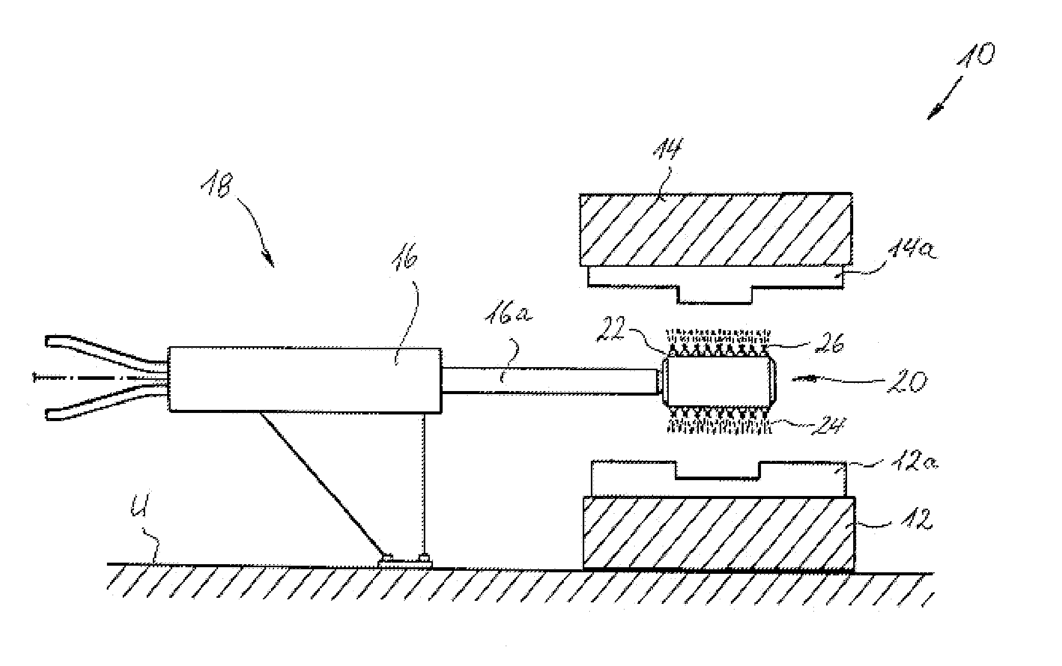
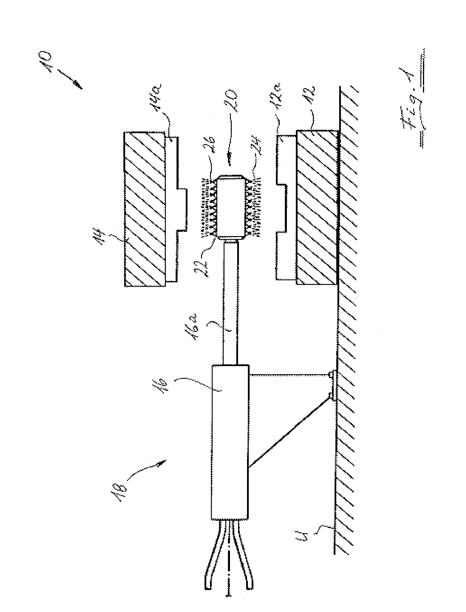
[0030]In a roughly schematic diagram, FIG. 1 shows a drop-forging device 10 as an example of a device for hot and cold shaping, in which the inventive spraying tool 20 may be used. The drop-forging device 10 comprises a lower press ram 12, which is fixedly mounted on a building floor U, and an upper press ram 14, which is movable back and forth by means of devices that are not shown here. In this way, the two mold halves 12a and 14a of the two press rams 12 and 14 may be brought close to one another to form a press space for shaping a workpiece or may be moved apart from one another to form a sufficient space for insertion of the spraying tool 20. The latter situation is illustrated in FIG. 1. To be able to insert the spraying tool 20 between the two mold halves 12a and 14a, it is mounted on the arm 16a of a robot 16, which is only shown in roughly schematic form in FIG. 1. Instead of a robot 16 having a robot arm 16a that can only be extended and / or shortened, as shown in FIG. 1, a...


PUM

PropertyMeasurementUnit
Elasticityaaaaaaaaaa

Abstract

The invention relates to a spraying tool, in particular as part of a mold-spraying device for spraying at least one section of a wall of a mold with working medium. In at least one embodiment, the spraying tool comprises a plurality of spraying elements for dispensing working medium, and at least one working-medium supply line which supplies working medium to the plurality of spraying elements. In accordance with at least one embodiment, at least some of the spraying elements, the spraying nozzles of which point downwards during operation, are equipped with a separate valve unit which is adjacent to the spraying nozzle and the valve element of which is prestressed elastically into a closed position in which it prevents the dispensing of working medium, but can be transferred under the action of a hydraulic and/or pneumatic pressure into an open position in which it permits the dispensing of working medium.

Description

CROSS-REFERENCE TO RELATED APPLICATIONS[0001]This application is a continuation of PCT application Serial No. PCT / EP2008 / 005499 filed on Jul. 4, 2008, which claims priority to German application Serial No. 10 2007 031 263.8 filed Jul. 5, 2007 which are hereby incorporated by reference in their entirety.BACKGROUND OF THE INVENTION[0002]1. Field of the Invention[0003]The invention relates to a spraying tool, in particular as part of a mold spraying device for spraying at least a section of a mold wall of a mold with a working medium, comprising:[0004]a plurality of spray elements for dispensing a working medium, and[0005]at least one working medium supply line, which supplies working medium to the plurality of spray elements.[0006]2. Background Art[0007]One possible application for using such a spraying tool is as a mold spraying device such as that used after a working cycle to prepare the walls of the mold halves of a drop-forging device for the next working cycle. To do so, the wal...

Claims


Application Information

Patent Timeline
IPC IPC(8): B05B1/14
CPCB05B1/3006B05B7/066F16N7/34B21J3/00B22D17/2007B21J1/06B21K29/00
Inventor KEIM, KARL-HEINRICH
Owner AED AUTOMATION
Why Eureka
Try Eureka