
Method of gas blow forming packaging and device for implementing same

Active Publication Date: 2010-07-15
TECHNOPLAN ENG
View PDF10 Cites 8 Cited by
  • Summary
  • Abstract
  • Description
  • Claims
  • Application Information

AI Technical Summary

Benefits of technology

[0021]More particularly, one subject of the present invention is a blow-molding machine with recovery of the blow-molding gas that is simple to operate and easy to adjust.
[0022]Another object of the invention is to optimize the blow-molding air recovery in the machine and to reduce its power consumption and the maintenance required.
[0023]A further object of the invention is to improve the recycling of the blow-molding gas.
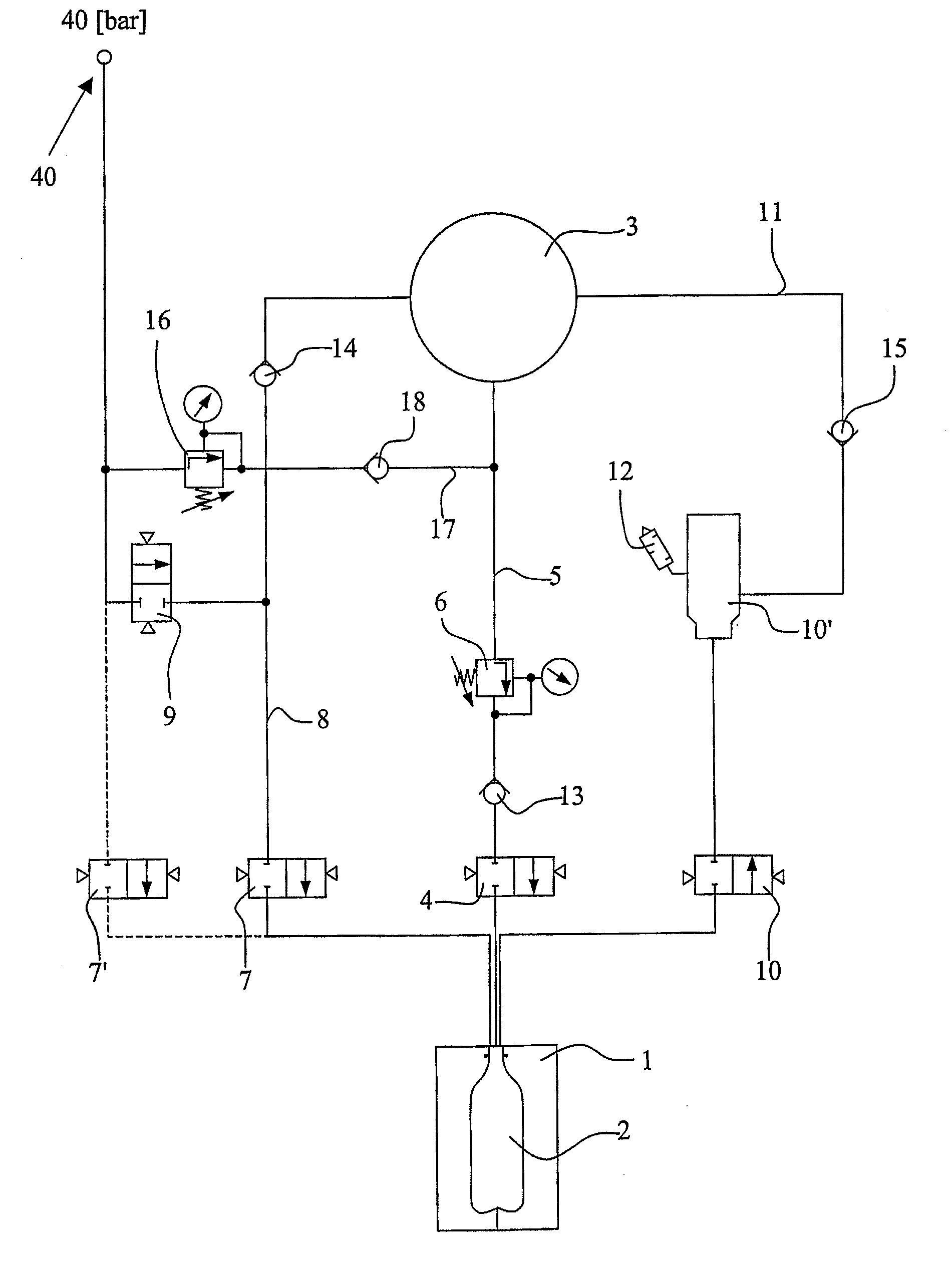
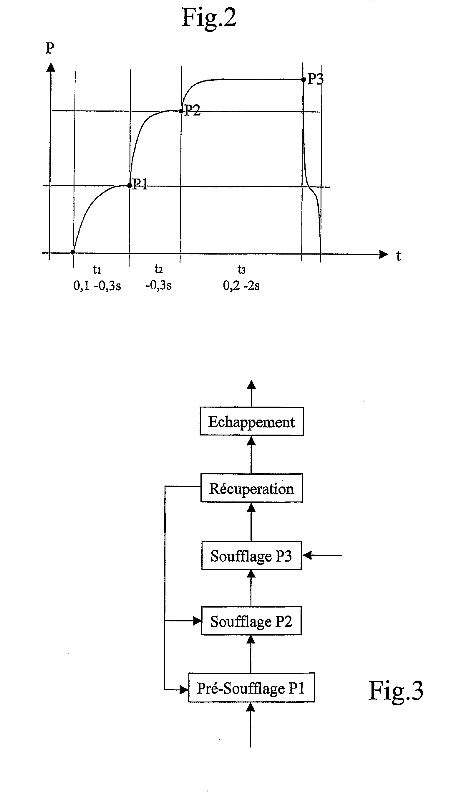
[0034]The advantage of the method and of the system according to the invention resides in the fact that the quantity of air, or of blow-molding gas, supplied by the recovery system is used not only for the pre-molding but also for carrying out a part of the blow-molding process. This results in both a better use of the recovered air, which is not regulated to a lower pressure in order to be recycled for example in the factory system or for actuating extruding tools, and also a reduction in the quantity of compressed air required to reach the pre-determined final pressure, since instead of going from the pre-molding pressure to the final blow-molding pressure, an intermediate blow-molding step is included, after the pre-molding step, which is generated by recovered gas.
[0035]Another advantage resides in the fact that the invention may be installed on existing machines which also reduces the modification costs.
[0041]With the system according to the invention, it is only necessary to provide a “top up” between the first blow-molding phase, this state being obtained with recovered gas only, and the final pressure of around 30 to 40 bar. In a given installation, this allows the electrical power consumption, or even the number of compressors used, to be reduced which results in a significant saving.

Problems solved by technology

Since the blow-molding pressure is always higher than the recovery pressure, it would not appear to be possible to use the recovered air for the blow-molding.

Method used


Image

  • Method of gas blow forming packaging and device for implementing same
  • Method of gas blow forming packaging and device for implementing same
  • Method of gas blow forming packaging and device for implementing same

Examples


Embodiment Construction

)

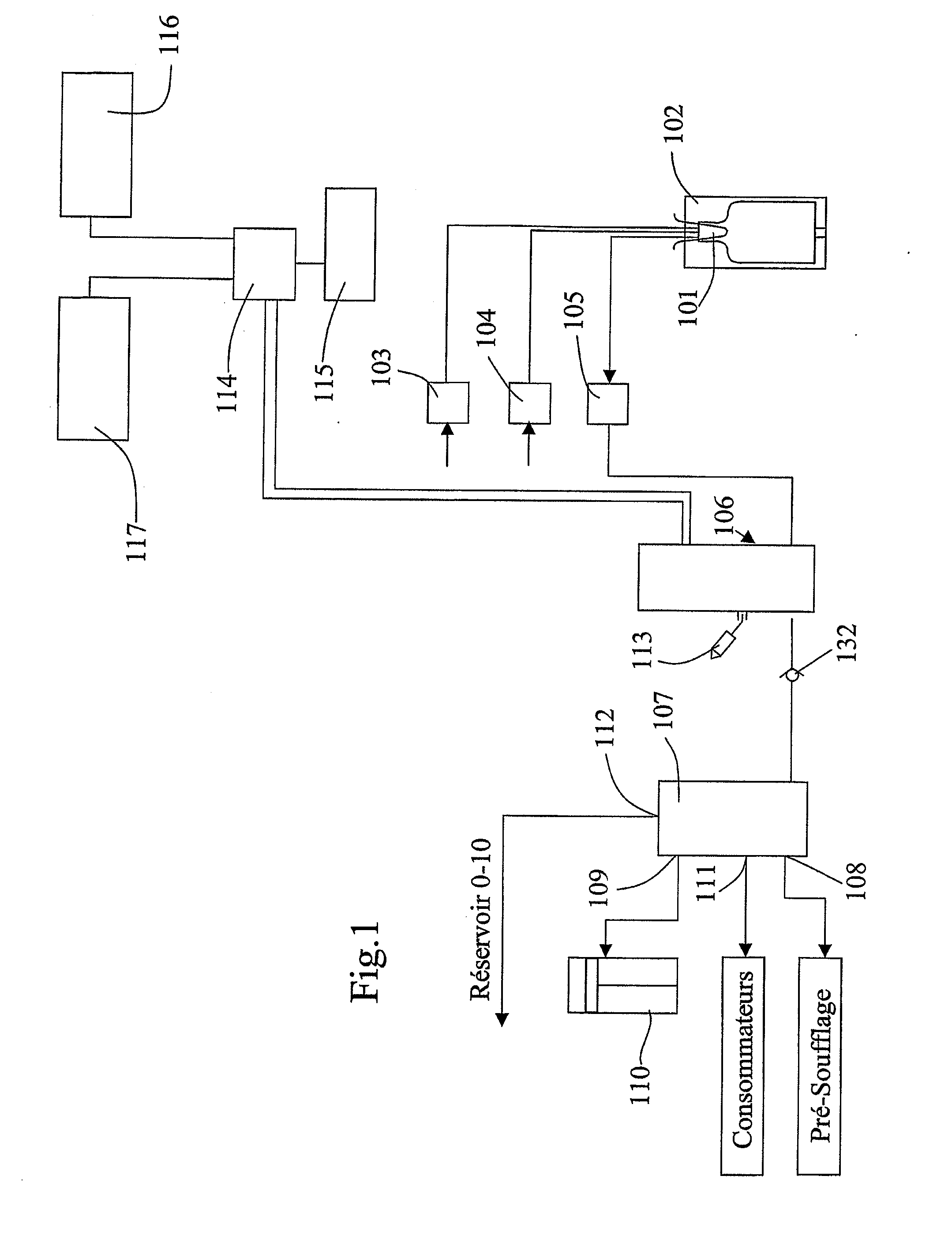
[0059]The principle of a blow-molding machine is first of all described with reference to FIG. 1. In this figure, the blow-molding machine is a machine known per se in the prior art and such as described in the publication WO 03 / 009993. In this machine, as indicated hereinabove, a gas, for example air, is supplied under a first pressure, referred to as pre-molding pressure, in the range between 4 and 16 bar, for the pre-molding of a preform 101 in the mold 102 via a pre-molding valve 103, then the gas is introduced under a second pressure, referred to as blow-molding pressure, of around 25 to 40 bar, for the blow-molding process itself of the packaging container in the mold 102, via a blow-molding valve 104. The blow-molding pressure depends in particular on the complexity of the packaging container to be blow-molded: the simpler the shape and without any particular details, the lower the blow-molding pressure can be. Once the container has been blow-molded, the gas in the containe...


PUM

PropertyMeasurementUnit
Timeaaaaaaaaaa
Timeaaaaaaaaaa
Timeaaaaaaaaaa

Abstract

The invention relates to a method of gas blow forming packaging in a mould using a preform and comprising recovery of the blow gas. The inventive method comprises the following steps consisting in: —) pre-blowing the gas into the preform at a first pressure (P1); —) blowing the gas into the pre-blown packaging at a second pressure (P2) which is greater than the first pressure (P1); —) blowing the gas into the partially-blown packaging at a third pressure (P3) which is greater than the second pressure (P2); —) recovering the gas in a recovery volume until a pre-determined pressure is obtained in the packaging or for a pre-determined period of time; —) using the recovered gas in order to preform pre-blowing operations and the first blowing step; and expanding the air that is free of residual gas in the packaging during and after the recovery phase. The invention also relates to a device that is used to implement said method.

Description

[0001]The present invention relates to a method for blow-molding a packaging container, such as a bottle, by means of a gas in a mold starting from a preform and for recovering the blow-molding gas for its reuse, and also to a device for implementing the method.[0002]The present invention also relates to a device for blow-molding packaging containers, in particular bottles, starting from a preform by means of a gas, such as air, and for recovering said gas for its reuse, comprising at least means for supplying the device with gas at a pre-molding pressure and at two blow-molding pressures, in order to implement the method.BACKGROUND OF THE INVENTION[0003]Numerous problems exist in the field of blow-molding installations for packaging containers, such as bottles, made of synthetic material. First of all, in order to effect the blow-molding of the containers into a mold, a gas, such as air, must be available under a high pressure of the order of 40 bar. In order to compress the requir...

Claims


Application Information

Patent Timeline
IPC IPC(8): B29C49/18
CPCB29C49/16B29C49/783B29C49/18Y02P70/10B29C49/42855B29C2049/7831B29C2049/7833
Inventor JOVER, DANIELSTORIONE, SAVINO
Owner TECHNOPLAN ENG
Learn More