Thermal Head, Method Of Manufacturing The Same, And Thermal Printer

Active Publication Date: 2006-05-11
KYOCERA CORP
View PDF4 Cites 8 Cited by
  • Summary
  • Abstract
  • Description
  • Claims
  • Application Information

AI Technical Summary

Benefits of technology

[0060] According to the invention, even if the substrate is wholly immersed in a cleaning solution in the process of cleaning the electrode layer, by virtue of interposition of the lower conductive protective film, it is possible to reduce the quantity of electrons tr

Problems solved by technology

As a result, the electrode layers could s

Method used


Image

  • Thermal Head, Method Of Manufacturing The Same, And Thermal Printer
  • Thermal Head, Method Of Manufacturing The Same, And Thermal Printer
  • Thermal Head, Method Of Manufacturing The Same, And Thermal Printer

Examples


Embodiment Construction

[0067] Now referring to the drawings, preferred embodiments of the invention are described below.

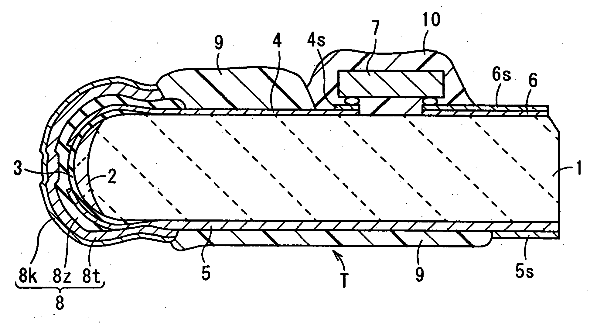
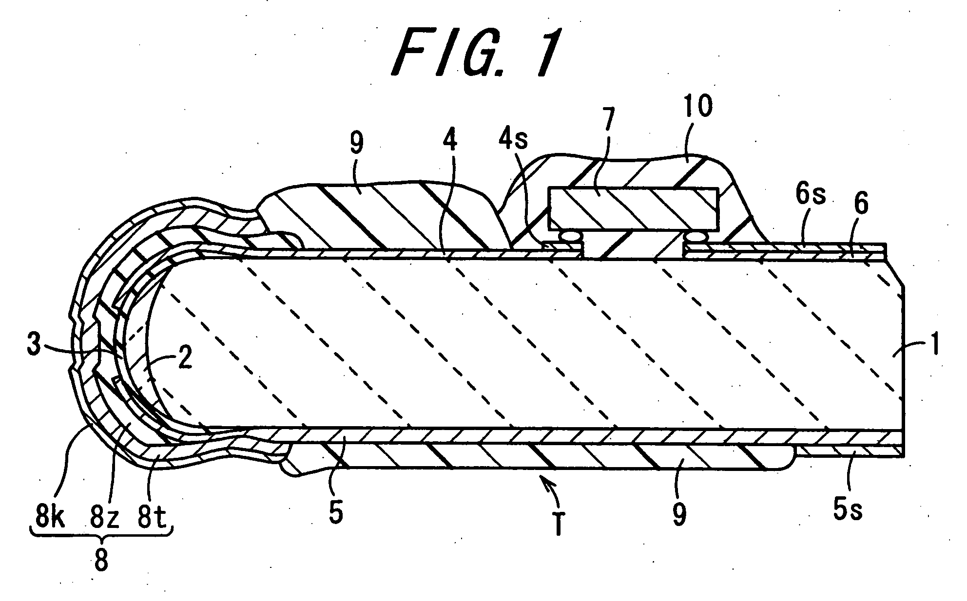
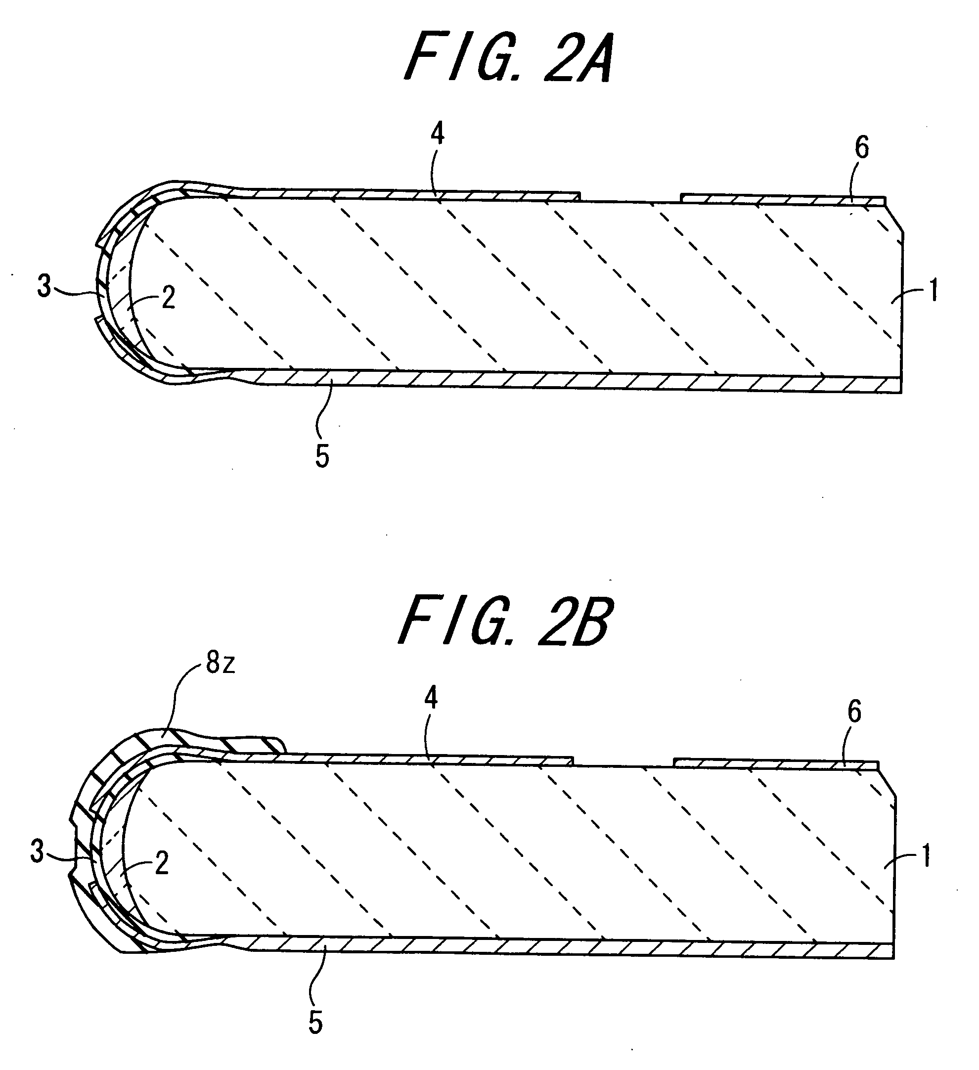
[0068]FIG. 1 is a sectional view of a thermal head according to one embodiment of the invention. The thermal head is mainly composed of: a substrate 1; a plurality of heater elements 3 made of tantalum nitride or the like; a discrete electrode layer 4 and a common electrode layer 5 made of aluminum (Al) or the like; and a driver IC 7. The substrate 1 has, at its end face, a glazed layer 2 made of glass or the like material. A plurality of heater elements 3 are laminated on the glazed layer 2. The discrete electrode layer 4 and the common electrode layer 5 are laminated on the upper surface and the lower surface of the substrate 1, respectively. The driver IC (Integrated Circuit) 7 selectively drives the heater elements 3 to generate Joule heat.

[0069] [Thermal Head]

[0070] In the invention, for example, the substrate 1 of the thermal head is formed of an electrically insulating material ...


PUM


Abstract

A thermal head in which battery effect-induced corrosion can be retarded while maintaining excellent anti-static capability in an upper conductive protective film, is provided. The thermal head includes a substrate, a heater element arranged on the surface of the substrate, an electrode layer connected to the heater element, and an upper conductive protective film for covering part of the electrode layer. In the thermal head, between the electrode layer and the upper conductive protective film is interposed a lower conductive protective film which is higher in specific resistance than the upper conductive protective film.

Description

BACKGROUND OF THE INVENTION [0001] 1. Field of the Invention [0002] The present invention relates to a thermal head that is incorporated into a printer mechanism, a thermal head manufacturing method, and a thermal printer. [0003] 2. Description of the Related Art [0004] As thermal heads of related art designed for incorporation into a printer mechanism, those as set forth hereunder have been known. [0005] For example, disclosed in Japanese Unexamined Patent Publication JP-A 61-154954 is a thin-film type thermal head constructed by laminating, on a substrate, a heater element, a wiring conductor layer, and an abrasion-resistant protective film successively in this order. In this thermal head, the abrasion-resistant protective film is designed to have a double-layer structure including a first protective film made of an SiN-based material which exhibits high insulation resistance, and a second protective film made of an SiC-based material or TiC-based material which exhibits low insul...

Claims


Application Information

Patent Timeline
IPC IPC(8): B41J2/05
CPCB41J2/3351B41J2/33515B41J2/33525B41J2/3353B41J2/33565
Inventor INOKUMA, YOSHIHIRO
Owner KYOCERA CORP
Why Eureka
Try Eureka