Image forming apparatus

Inactive Publication Date: 2010-03-04
CANON KK
View PDF1 Cites 0 Cited by
  • Summary
  • Abstract
  • Description
  • Claims
  • Application Information

AI Technical Summary

Benefits of technology

[0009]In the view of the above-described state of the art, an exemplary embodiment of the present invention provides a technique for cutting the loss time caused when the printing operation is postponed, and for reducing the FPOT.

Problems solved by technology

However, when the above-described parallel processing method is employed and a long time is taken to execute the image expansion by the controller, there is a possibility that the image expansion is not completed until the timing at which the engine starts the printing operation.
In that case, the engine cannot receive the image information and hence cannot execute the printing operation, thus resulting in a print error.
Thus, when the printing operation is postponed and the image expansion is completed in the controller during the idle rotation of the transfer drum, the time taken for the remaining idle rotation of the transfer drum becomes a loss time and the FPOT is prolonged.

Method used


Image

  • Image forming apparatus
  • Image forming apparatus
  • Image forming apparatus

Examples


first exemplary embodiment

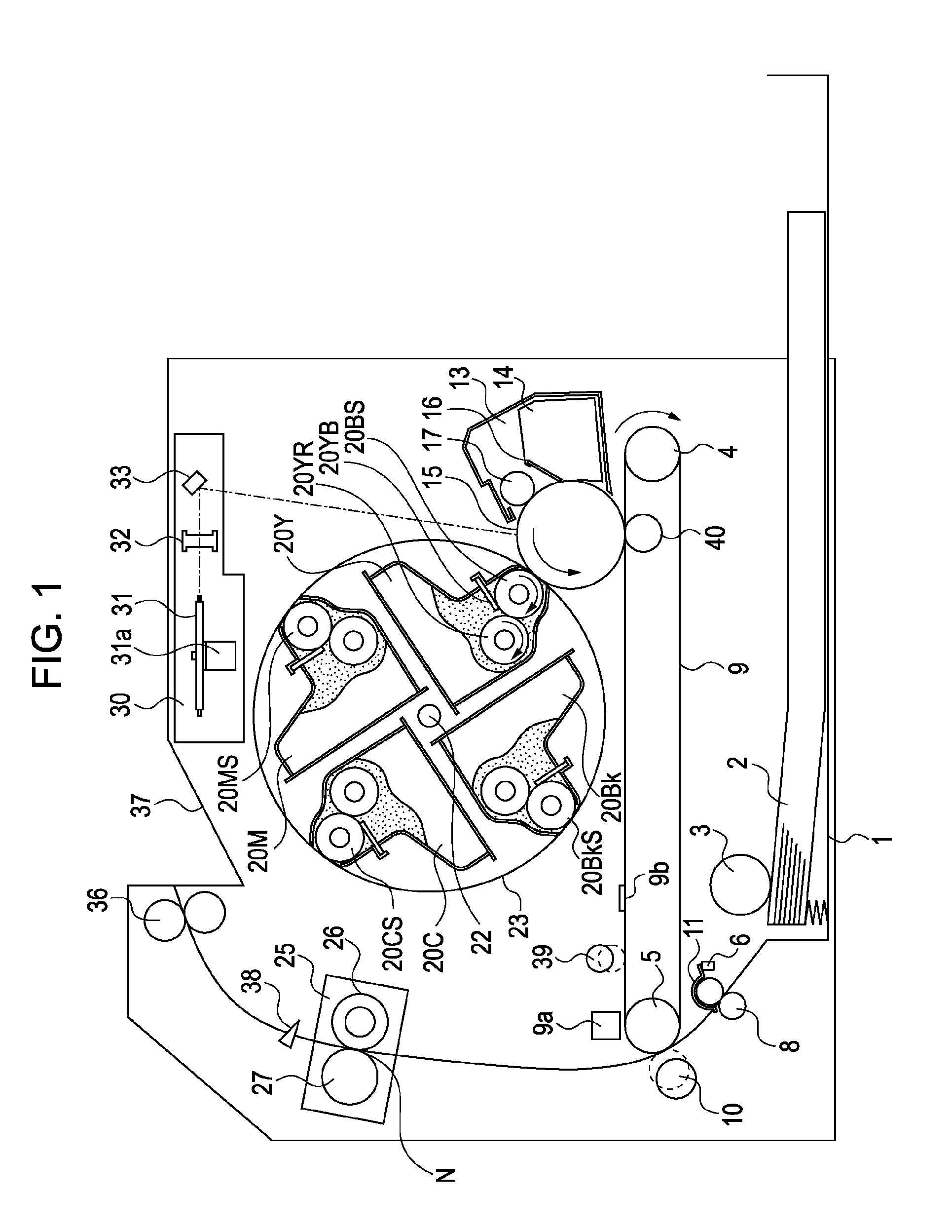
[0025]FIG. 1 is a schematic view illustrating an example of an entire construction of a laser beam printer (color image forming apparatus) according to a first exemplary embodiment of the present invention. Detailed constructions of various components are first described in sequence of operations.

(Charging Section)

[0026]A drum unit 13 has an integral structure including an electrophotographic photosensitive member (hereinafter referred to as a “photosensitive drum”) 15 which is a drum-shaped image bearing member, and a cleaning container 14 which is a cleaning apparatus serving also as a holder for the photosensitive drum 15. The drum unit 13 is detachably attached to a main body of the image forming apparatus such that the drum unit 13 is easily replaceable in agreement with the life of the photosensitive drum 15. Around the photosensitive drum 15, there are disposed a cleaner blade 16 and an electro-conductive roller 17 which serves as a primary charging unit. The photosensitive d...

second exemplary embodiment

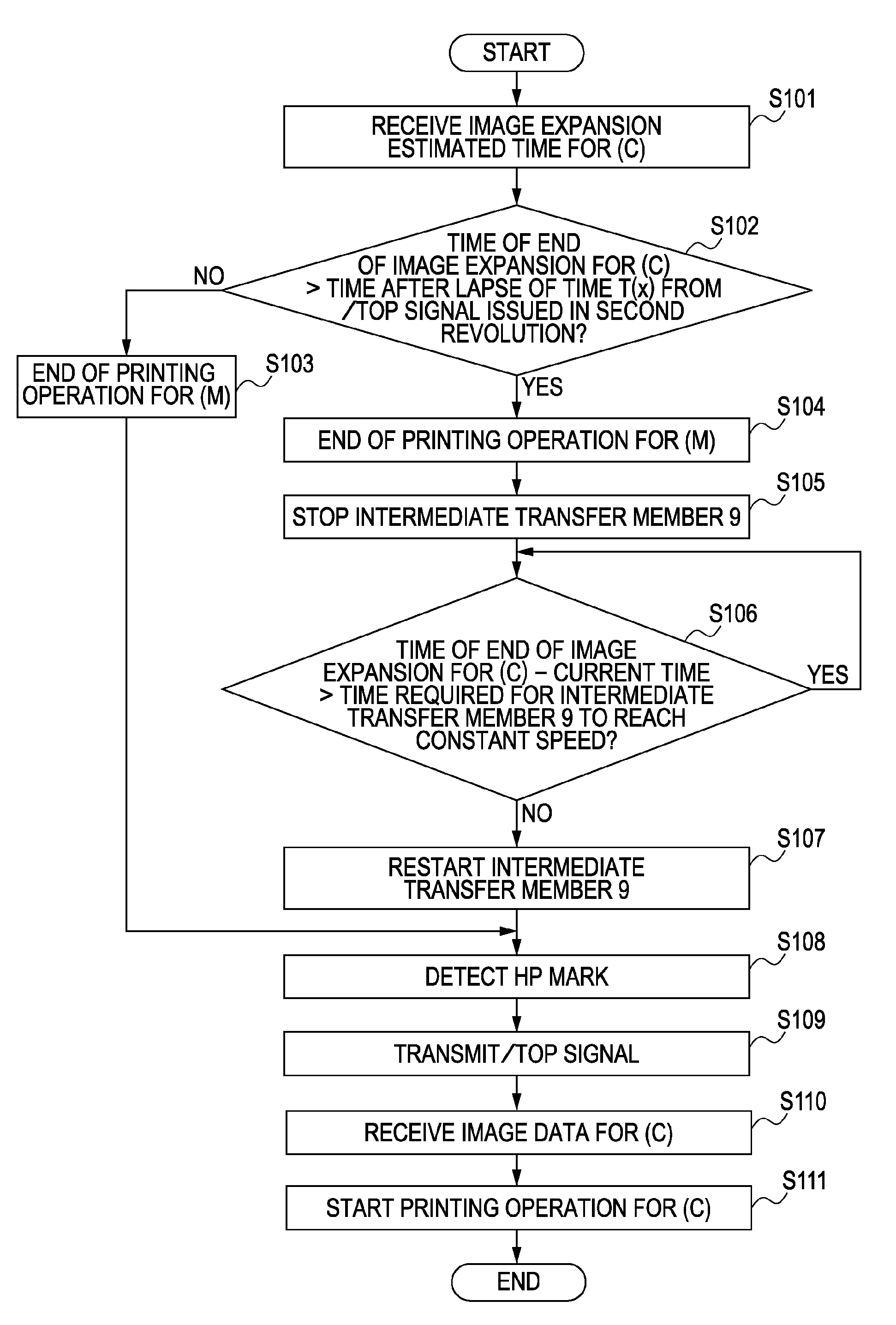
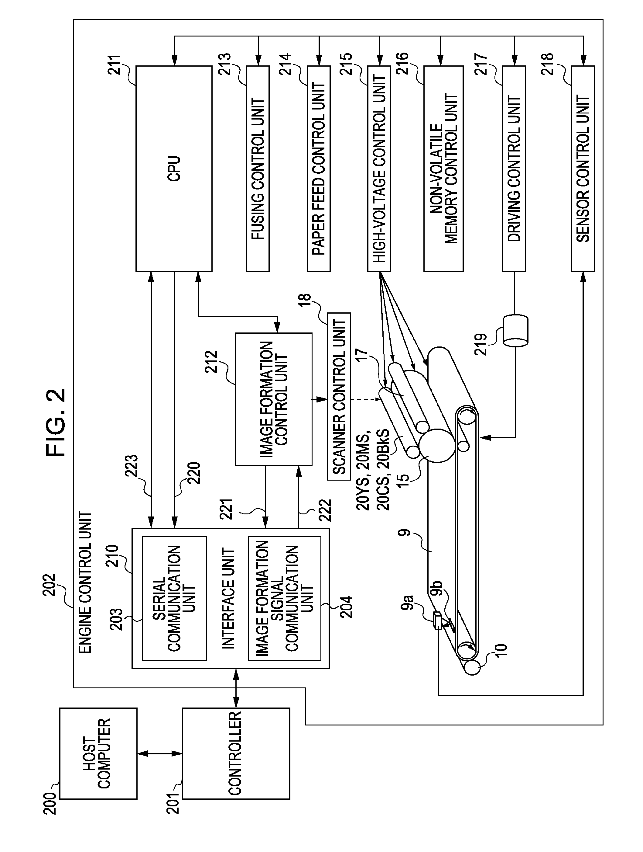
[0091]A second exemplary embodiment can be practiced in the same configurations as those, illustrated in FIGS. 1 and 2, which have been described above in connection with the first exemplary embodiment, and hence a detailed description of the configurations is omitted. The second exemplary embodiment is intended to postpone the printing operation without idly revolving the intermediate transfer member 9 as in the first exemplary embodiment. However, the second exemplary embodiment differs from the first exemplary embodiment in that the printing operation is postponed by decelerating the driving speed of the intermediate transfer member 9 instead of stopping the intermediate transfer member 9.

[0092]FIG. 5 is a timing chart when the printing operation is postponed by decelerating the intermediate transfer member 9 without idly revolving it, and then returning the intermediate transfer member 9 to the constant speed. Processes from 501 to 507 are the same as those from 301 to 307 descr...

third exemplary embodiment

[0108]A third exemplary embodiment can be practiced in the same configurations as those, illustrated in FIGS. 1 and 2, which have been described above in connection with the first exemplary embodiment, and hence a detailed description of the configurations is omitted. In the third exemplary embodiment, the driving speed of the intermediate transfer member 9 is variably controlled to postpone the printing operation by idly revolving the intermediate transfer member 9. The reason why the intermediate transfer member 9 is idly revolved unlike the above-described first and second exemplary embodiments resides in that the printing operation cannot be properly postponed only by control, which does not include the idle revolution, depending on the size of the recording medium 2. Stated another way, when the difference between the size of the recording medium 2 and the length of the intermediate transfer member 9 is small, a time from the end of the primary transfer for the previous color t...


PUM


Abstract

A color image forming apparatus includes one image bearing member, an image forming unit configured to successively form images with toners in plural different colors on the image bearing member per color, a revolving intermediate transfer member, and a transfer unit configured to successively transfer the images on the image bearing member onto the intermediate transfer member in a superimposed relation in a transfer section. Images are transferred in a superimposed relation by executing control such that, when formation of the next image is not started at a due timing of starting the formation of the next image, a timing at which transfer is started after the formation of the next image and a timing at which a leading end of the previously transferred image reaches the transfer section are matched with each other by temporarily changing the revolving speed of the intermediate transfer member or stopping it.

Description

BACKGROUND OF THE INVENTION[0001]1. Field of the Invention[0002]The present invention relates to an image forming apparatus, such as a copying machine, a laser beam printer, or a facsimile.[0003]2. Description of the Related Art[0004]In a known image forming apparatus, such as a copying machine or a laser beam printer, when one color image is formed, a controller analyzes information from an external apparatus, e.g., a computer, and executes image expansion (transform) to image information per yellow, magenta, cyan and black. Further, an engine controls a printing operation of successively forming toner images on a photosensitive drum based on the image information obtained with the image expansion by using toners of yellow, magenta, cyan and black, and further executing multi-transfer of the toner images onto an intermediate transfer member.[0005]A method for reducing a first print-out time (hereinafter referred to as “FPOT”) is proposed which executes the image expansion and the p...

Claims


Application Information

Patent Timeline
IPC IPC(8): G03G15/16
CPCG03G15/0131G03G2215/0177G03G15/1605
Inventor ISHIDA, SATOSHI
Owner CANON KK
Why Eureka
Try Eureka