Adjustable gas damping vibration and shock isolation system

a technology of shock isolation system and adjustable gas, which is applied in the direction of shock absorbers, navigation instruments, instruments, etc., can solve the problems of difficult design and manufacture of common imu that will satisfy multiple applications

Inactive Publication Date: 2010-03-11
HONEYWELL INT INC
View PDF6 Cites 31 Cited by
  • Summary
  • Abstract
  • Description
  • Claims
  • Application Information

AI Technical Summary

Problems solved by technology

Further, depending on the application, the vibration and shock environments to which the IMUs are subjected may be drastically different, this makes it difficult to design and manufacture a common IMU that will satisfy multiple applications.

Method used


Image

  • Adjustable gas damping vibration and shock isolation system
  • Adjustable gas damping vibration and shock isolation system

Examples


Embodiment Construction

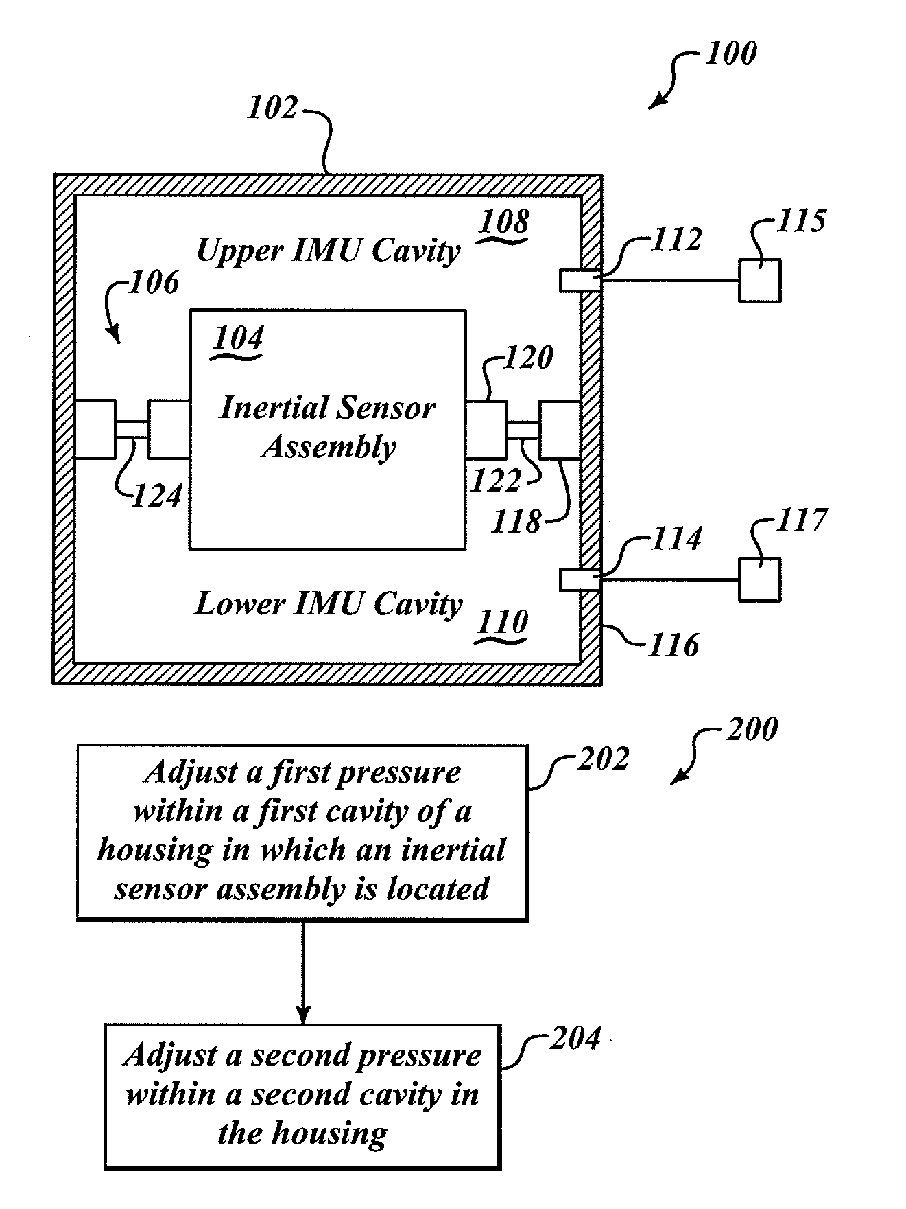
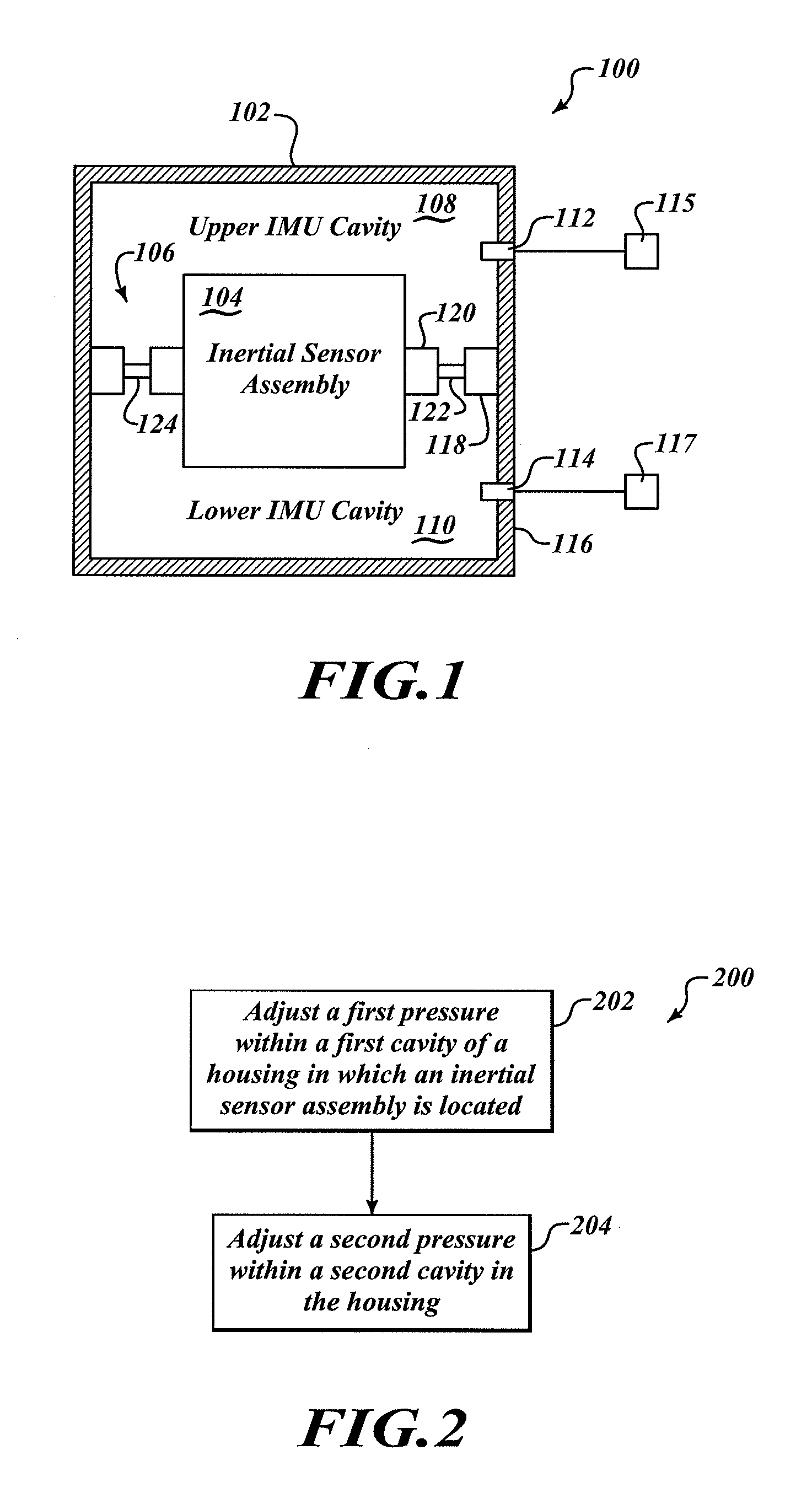
[0011]FIG. 1 schematically shows an inertial measurement unit (IMU) 100 having a housing 102. Located within the housing 102, an inertial sensor assembly 104 (otherwise referred to as an inertial cluster) is coupled to a vibration isolator assembly 106. The arrangement of the IMU 104 coupled to the vibration isolator assembly 106 creates a first cavity 108 (e.g., upper cavity as illustrated) and a second cavity 110 (e.g., lower cavity as illustrated) within the housing 102.

[0012]The housing 102 includes openings 112, 114 that extend through the housing wall 116. The openings 112, 114 permit fluid, generally a gas such as air or Nitrogen, to be exchanged between the respective cavities 108, 110 and at least one external pressure source (not shown). One purpose of the openings 112, 114 is to adjust the pressure in each cavity and thereby tune the IMU 100 to have a desired natural frequency. Another purpose of the cavities 108, 110 and the openings 112, 114 is to control or even optimi...


PUM


Abstract

An inertial measurement unit includes a housing with openings to permit fluid communication between at least one pressure source and two distinct cavities within the housing. The cavities are separated by an inertial sensor assembly coupled to a vibration isolator assembly. The pressure in the cavities may be adjusted or tuned to change a natural frequency of the inertial measurement unit, thus allowing the unit to be configured and even optimized for a variety of different applications. By adjusting the pressure in the respective cavities, gas squeeze film damping effects may be optimized when the inertial measurement unit undergoes a shock event and / or when the inertial measurement unit experiences vibration loads during operation. In one embodiment, the vibration isolator assembly includes perforations to permit fluid communication between the first and second cavities during specific operational events.

Description

BACKGROUND OF THE INVENTION[0001]Inertial measurement units (IMUs) are used in a variety of applications. An IMU is the main component of inertial guidance systems used in air and space vehicles, watercraft vehicles and guided missiles. IMUs work by detecting the current rate of acceleration, as well as changes in rotational attributes, including pitch, roll and yaw using a combination of accelerometers and gyroscopes. The data collected from these sensors allows a computer to track a vehicle's position using a method known as dead reckoning. The term IMU commonly refers to a box containing three accelerometers and three gyroscopes. The accelerometers are placed such that their measuring axes are orthogonal to each other so they can measure inertial acceleration, also known as G-forces.[0002]The performance of an IMU is dependent on the vibration a shock isolation of its inertial sensor(s) within the units. Further, depending on the application, the vibration and shock environments ...

Claims


Application Information

Patent Timeline
Patent Type & Authority Applications(United States)
IPC IPC(8): F16F9/00
CPCF16F15/0232G01C21/16F16F15/0237G01C21/166
Inventor GOEPFERT, SCOTT J.BRAMAN, TODD L.SCHLAGER, MATTHEWWEINMANN, JACOB
Owner HONEYWELL INT INC
Why Eureka
Try Eureka