
Battery post clamp

a battery post and clamping technology, applied in the direction of electrical connections, electrical connection structural associations, connections, etc., can solve the problems of not providing uniform coupling of the connector prior art not providing separate coupling of the secondary connection to the battery post, etc., to reduce the loss of ir during energy transfer and shorten the interconnection of batteries

Inactive Publication Date: 2010-03-11
FELDMAN THOMAS H
View PDF4 Cites 0 Cited by
  • Summary
  • Abstract
  • Description
  • Claims
  • Application Information

AI Technical Summary

Benefits of technology

[0006]A pair of spaced apart bolts are provided with each bolt passing through jaw sides transverse to the battery post. The use of spaced apart bolts, each being transverse to the battery post, enables the capture of the battery post uniformly in the jaws which is otherwise not possible with prior art devices.
[0007]Each of the bolts have a head on one end thereof and a nut on an opposite end thereof enabling uniform tightening of the jaws against the battery post and enabling attachment of cables to the jaws in a parallel relationship with respect to one another.
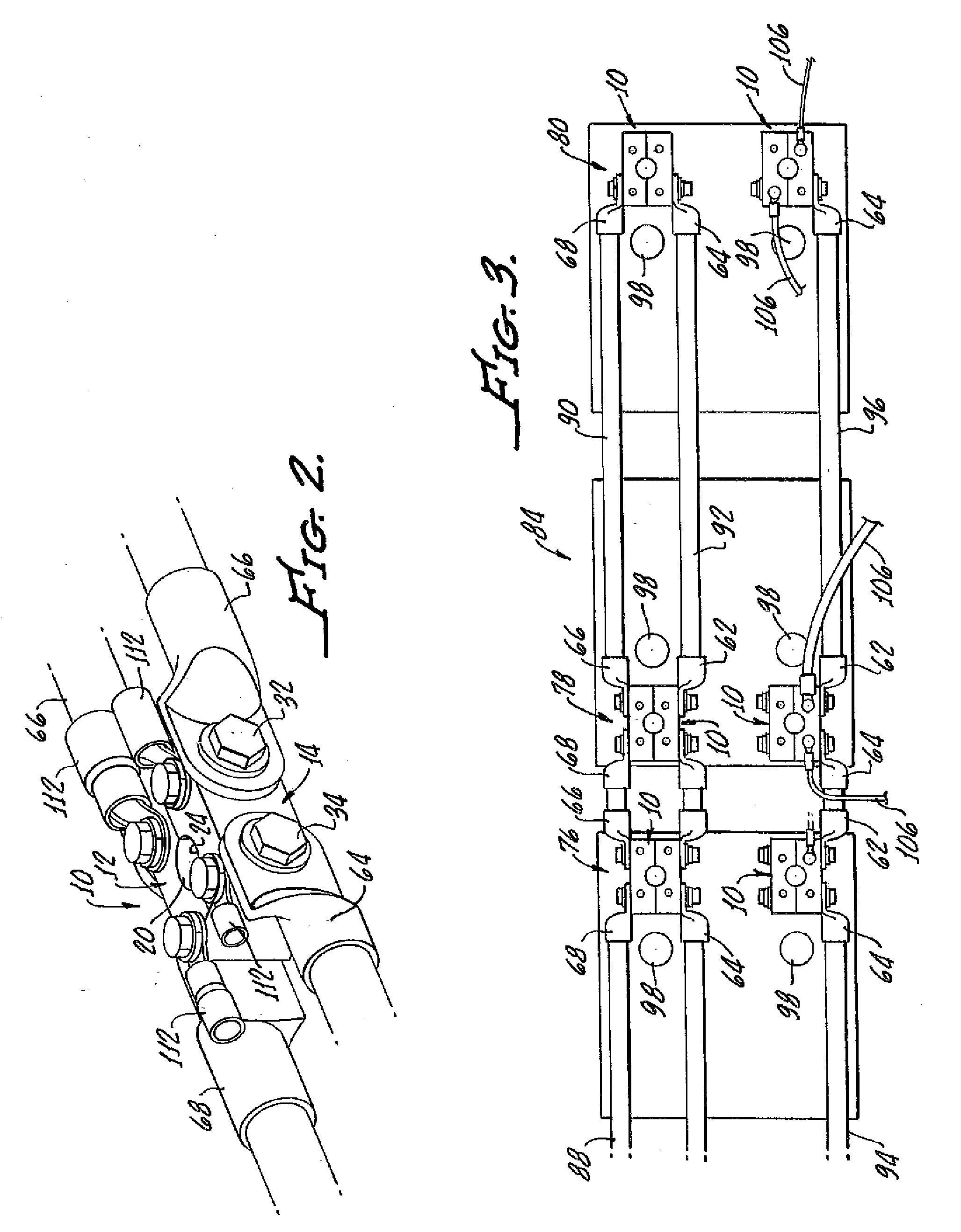
[0008]This parallel relationship is important in connecting a multitude of batteries in marine environments and for enabling shorter interconnection of batteries which thus reduces IR loss during transfer of energy from the batteries to an engine in a starting mode.
[0009]Preferably, the bolts are parallel to one another in order to provide uniform engagement, or grasping of the battery opposed to by the jaws.

Problems solved by technology

Unfortunately, battery terminal connectors which have a slit or hinged gripping portion, which is clamped to a battery post, do not provide uniform coupling of the connector to the battery post.
In addition, the prior art does not provide for a coupling of secondary connections to the battery post separate from the primary connector which provides power for the principal function of the RV, automobile, or marine vessel.

Method used


Image

  • Battery post clamp
  • Battery post clamp
  • Battery post clamp

Examples


Embodiment Construction

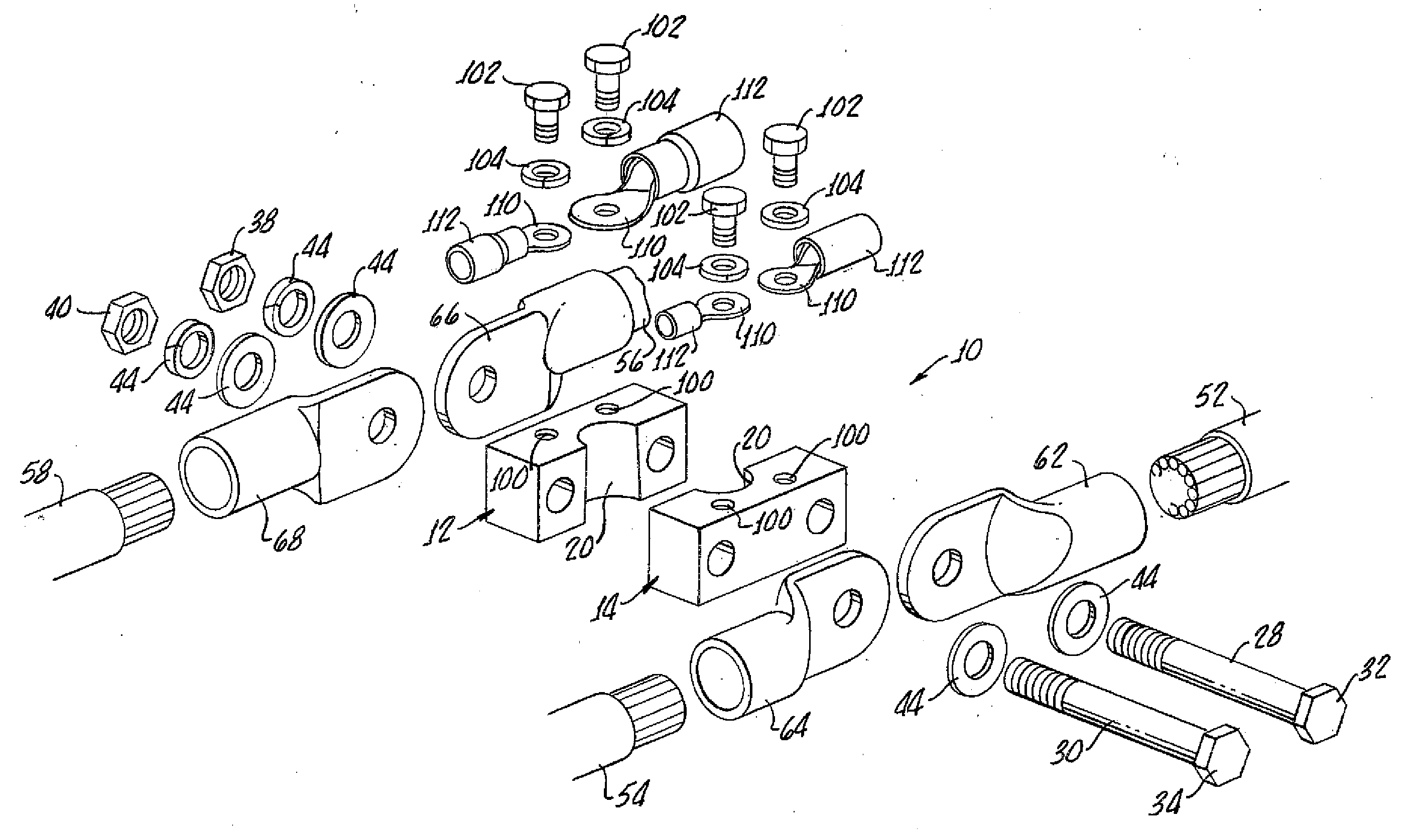
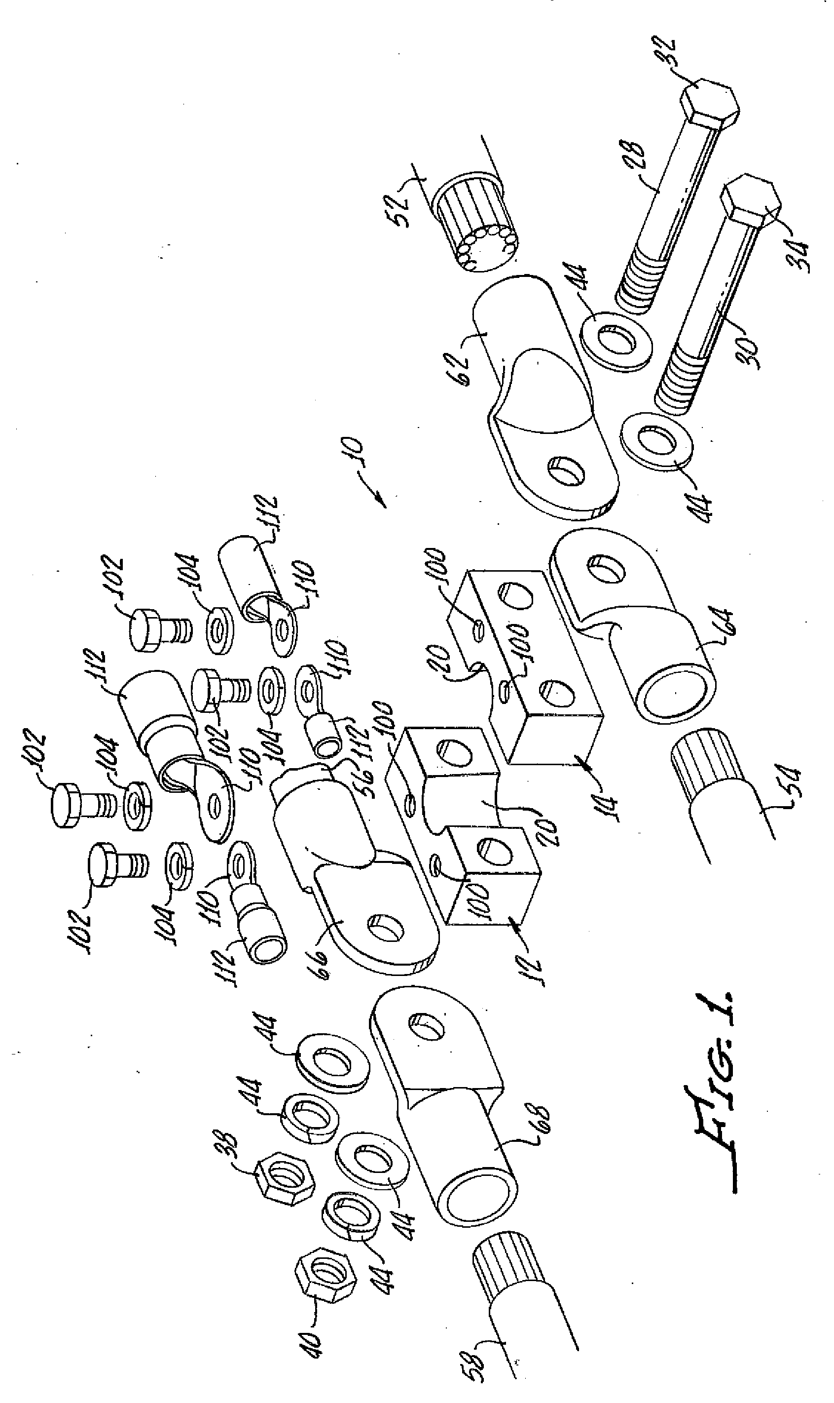
[0018]With reference to FIGS. 1-3, a battery post connector 10 in accordance with the present invention includes a pair of generally rectilinear jaws 12, 14 sized and shaped to fit against a conventional battery post, not shown, with the jaws 12, 14 being abuttable with notches 20, 22 facing one another to encompass the battery post, not shown. The notches 20, 22 further may include a ten percent slope to accommodate a conventional tapered battery post, not shown.

[0019]A pair of spaced apart bolts 28, 30 each including a head 32, 34 and a nut 38, 40 along with optional washers 44 enable tightening of the jaws 12, 14 against the battery post, not shown, as illustrated in FIG. 2.

[0020]The bolts 28, 30, enable attachment of cables 52, 54, 56, 58 by way of conventional connectors 62, 64, 66, 68 to the jaws 12, 14 in a generally parallel relationship with one another as not only illustrated in FIGS. 1 and 2, but further shown in FIG. 3.

[0021]It should be appreciated that additional conne...


PUM


Abstract

A battery post connector and harness in accordance with the present invention includes a pair of generally rectilinear jaws with each jaw having a peripheral notch sized and shaped to fit against a battery post. The jaws are abuttable with the notches facing one another to encompass the battery post. A pair of spaced apart bolts are provided with each bolt passing through the jaw transverse to the battery post and each bolt includes a head on one end thereof and a nut on the other end thereof for tightening jaws against the battery post. This enables the bolt to attach the cables to the jaws in a parallel relationship with respect to one another.

Description

[0001]The present invention generally relates to a battery terminal connector and more particularly is directed to a battery terminal connector that enables multiple batteries to be connected in a spaced conserving manner particularly useful in a marine environment.[0002]Prior art battery terminal connectors for connecting one or more electrical cables to a battery post have included elastically formable gripping portions which are slit so that the gripping portion can be opened and closed around the battery post.[0003]Unfortunately, battery terminal connectors which have a slit or hinged gripping portion, which is clamped to a battery post, do not provide uniform coupling of the connector to the battery post.[0004]In addition, the prior art does not provide for a coupling of secondary connections to the battery post separate from the primary connector which provides power for the principal function of the RV, automobile, or marine vessel. A battery post connector in accordance with...

Claims


Application Information

Patent Timeline
Patent Type & Authority Applications(United States)
IPC IPC(8): H01R11/01
CPCH01R11/285
Inventor FELDMAN, THOMAS H.
Owner FELDMAN THOMAS H
Learn More