Oil feed type auto-tensioner

a technology of oil feed and auto-tensioner, which is applied in the direction of belt/chain/gearing, mechanical equipment, belts/chains/gearings, etc., can solve the problems of serration-shaped threads, high manufacturing cost, chain cutting, etc., and achieve low cost and simple structure

Inactive Publication Date: 2010-03-11
NTN CORP
View PDF9 Cites 5 Cited by
  • Summary
  • Abstract
  • Description
  • Claims
  • Application Information

AI Technical Summary

Problems solved by technology

In the oil feed type auto-tensioner disclosed in Patent document 1, if the plunger protrudes excessively from the cylinder chamber due to excessive vibration of the chain, the plunger cannot retract sufficiently thereafter when the engine speed subsequently drops, thus resulting in cutting of the chain due to over-tensioning or damage to the ratchet.
Also, because it is necessary to form the rack on the outer periphery of the plunger, the manufacturing cost is high.
But forming the serration-shaped threads is troublesome and thus the manufacturing cost is high, as with the auto-tensioner disclosed in Patent document 1.
Also, it is troublesome to form the circumferential grooves in the outer periphery of the plunger, and thus the manufacturing cost is high.

Method used


Image

  • Oil feed type auto-tensioner
  • Oil feed type auto-tensioner
  • Oil feed type auto-tensioner

Examples


Embodiment Construction

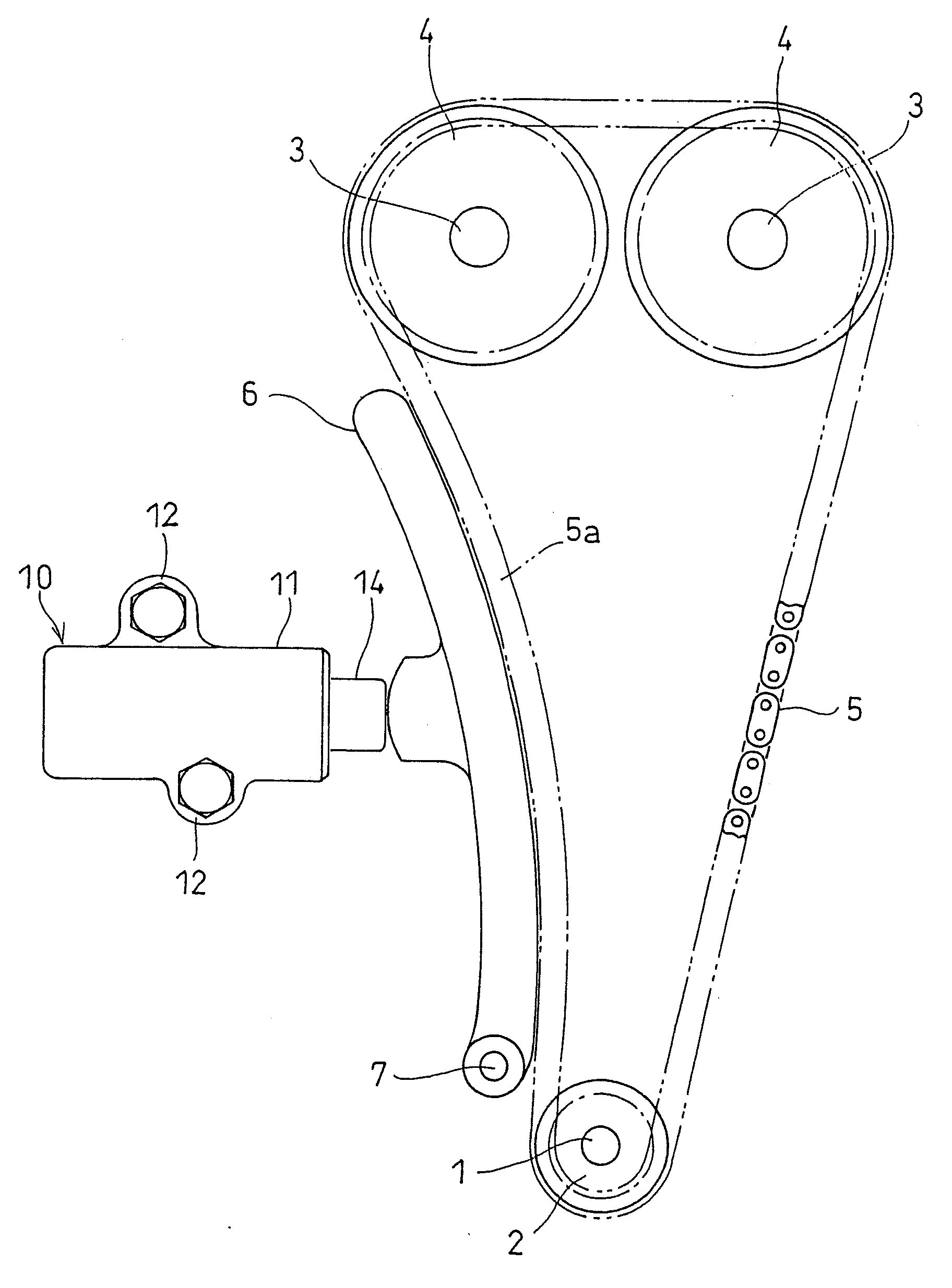
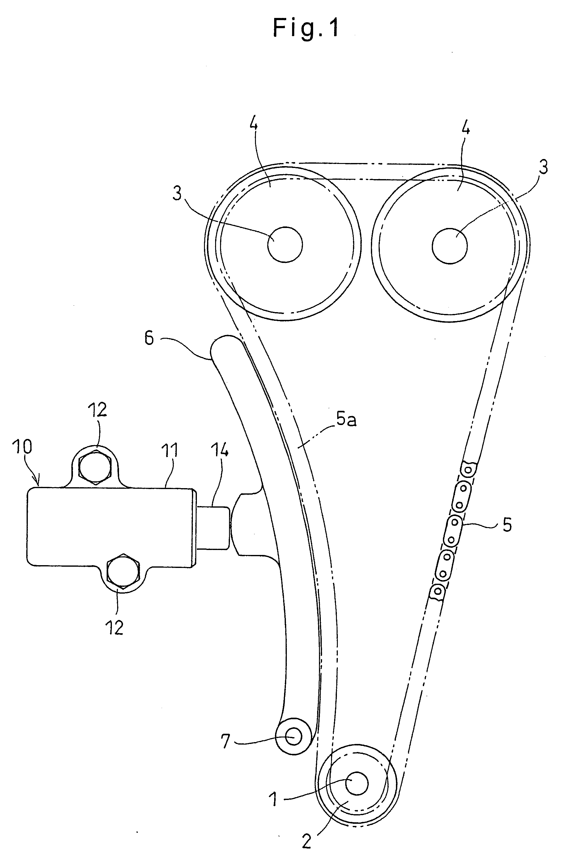
[0049]The embodiments of this invention are now described with reference to the drawings. FIG. 1 shows a chain tension adjusting device for adjusting the tension of a chain for driving camshafts. This device includes a sprocket 2 mounted to an end of a crankshaft 1, sprockets 4 each mounted to an end of one of camshafts 3, and a chain 5 trained around the sprockets 2 and 4. A chain guide 6 is provided on the slack side of the chain 5.

[0050]The chain guide 6 has its bottom end supported by the shaft 7 so as to be pivotable about the shaft 7. The chain guide 6 is pressed against the chain by an adjusting force applied to the chain guide 6 from an oil feed type auto-tensioner 10.

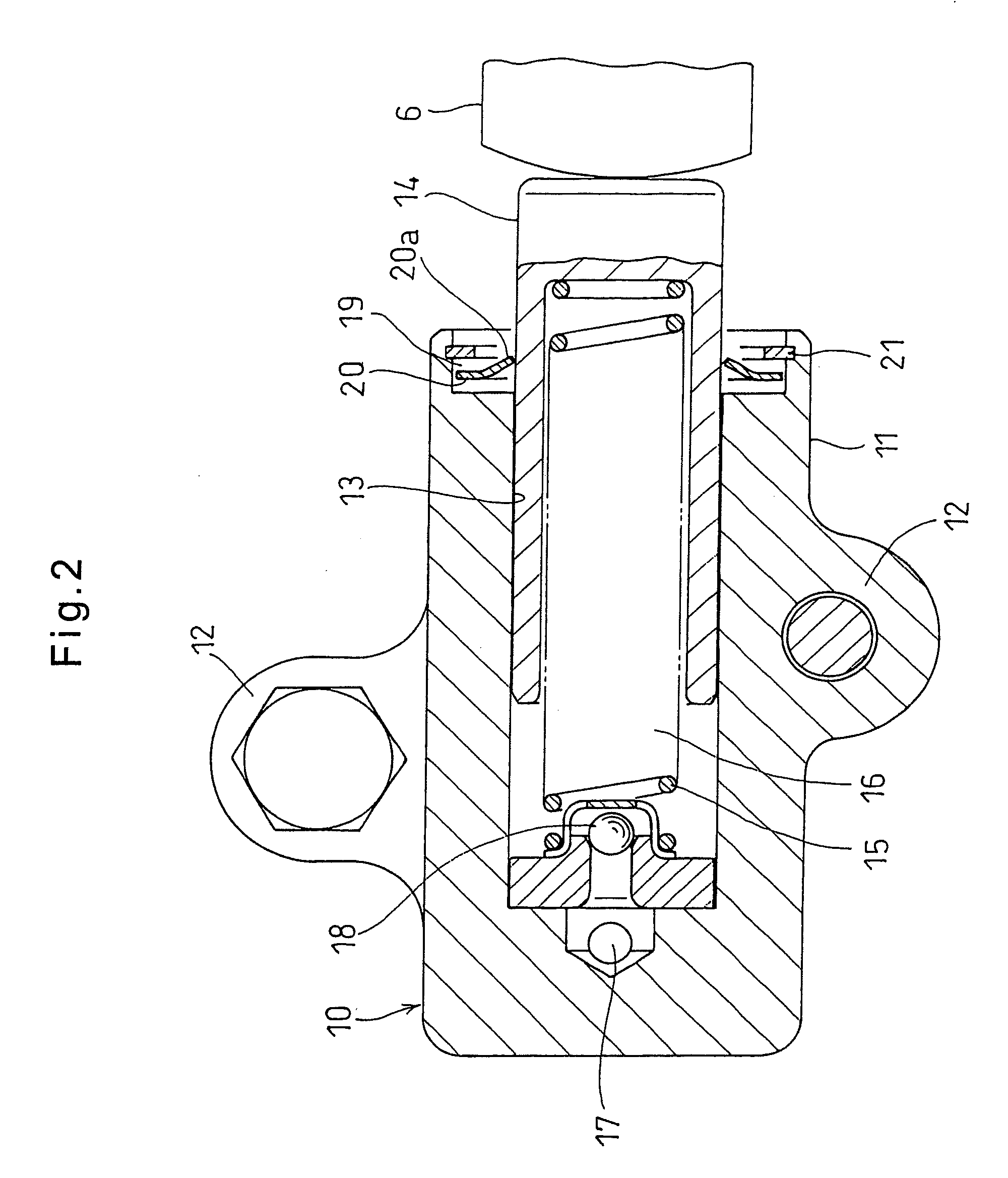
[0051]As shown in FIG. 2, the oil feed type auto-tensioner includes a housing 11. As shown in FIG. 1, the housing 11 has mounting pieces 12 on its outer periphery which are bolted to an engine block. The housing 11 defines a cylinder chamber 13 having an opening at one end of the housing 11. A plunger 14 is sli...


PUM


Abstract

An object is to provide an oil feed type auto-tensioner which can reliably prevent air from mixing into hydraulic oil in the pressure chamber.This tensioner includes a housing (11) defining a cylinder chamber (13), a plunger (14) slidably mounted in the cylinder chamber (13), a return spring (15) mounted in the cylinder chamber (13) and biasing the plunger (14) outwardly of the cylinder chamber (13), the housing (11) being formed with an oil supply passage (17) communicating with a pressure chamber (16) defined in the cylinder chamber behind the plunger (14), and a check valve (18) provided at a hydraulic oil outlet of the oil supply passage (17). The cylinder chamber (13) includes a large-diameter hole portion (19) provided at an open end thereof, in which a snap ring (20) for braking is received so as to be movable therein. The snap ring (20) includes a plurality of engaging pieces (20a) provided at a radially inner portion thereof and inclined in a direction in which the plunger (14) protrudes from the housing. The engaging pieces (20a) have radially inner edges that are in engagement with the outer periphery of the plunger, thereby restraining retraction of the plunger. When a pushing force is applied to the plunger (14) from the chain while the engine is at a stop, the snap ring (20) for braking abuts the closed end face of the large-diameter hole portion (19) and is stopped. In this state, because the radially inner edges of the engaging pieces (20a) formed on the radially inner portion of the snap ring (20) are in engagement with the outer periphery of the plunger (14), the plunger (14) is prevented from retracting, thus keeping the tension of the chain within a predetermined range. This prevents the plunger (14) from markedly moving outwardly when the engine is subsequently restarted.

Description

TECHNICAL FIELD[0001]This invention relates to an oil feed type auto-tensioner for keeping constant the tension of a timing belt or a timing chain for driving camshafts.BACKGROUND ART[0002]Typically, an auto-tensioner is used in a chain transmission device including a timing belt or a timing chain (hereinafter simply referred to as the “chain”) through which the engine rotation is transmitted to camshafts to keep the tension of the chain constant by applying its adjusting force to the slack side of the chain.[0003]One known auto-tensioner of this type includes a housing, a plunger slidably inserted in a cylinder chamber defined in the housing for pressing the chain, and a return spring also mounted in the cylinder chamber and biasing the plunger outwardly of the cylinder chamber. The housing is formed with an oil supply passage communicating with a pressure chamber defined in the cylinder chamber behind the plunger. A check valve is provided at the hydraulic oil outlet of the oil su...

Claims


Application Information

Patent Timeline
Patent Type & Authority Applications(United States)
IPC IPC(8): F16H7/08
CPCF16H7/0836F16H7/0848F16H2007/0806F16H2007/0859F16H2007/0814F16H2007/0846F16H2007/0812
Inventor YAMAMOTO, KEN
Owner NTN CORP
Why Eureka
Try Eureka