Expandable Intervertebral Prosthesis Device for Posterior Implantation and Related Method Thereof

an intervertebral prosthesis and expandable technology, applied in the field of expandable intervertebral prosthesis devices for posterior implantation, can solve the problems of specialized access methods that can be deemed dangerous by some surgeons, bulky conventional cages, and inability to be inserted from the back

Inactive Publication Date: 2010-03-11
UNIV OF VIRGINIA ALUMNI PATENTS FOUND
View PDF0 Cites 31 Cited by
  • Summary
  • Abstract
  • Description
  • Claims
  • Application Information

AI Technical Summary

Benefits of technology

[0006]Some of the exemplary aspects of the present invention low profile expandable cage provide, but not limited thereto, the following features and advantages:
[0011]The expansion chambers of such cage bodies may be emptied in their collapsed stage so that the injection of cement does not lead to any air or bubble during expansion that could make the construction more fragile.
[0014]Due to the minimal height of the cage in its collapsed phase of the present invention, no dangerous manipulation of the dural sac is necessary.
[0015]The manipulation of the present invention cage into the vertebral body defect does not require a bulky cage holder that is always dangerous for the spinal cord

Problems solved by technology

Theses conventional cages are bulky and cannot be inserted from the back without an extended posterior or posterolateral approach to the spine and very specialized access methods that can be deemed dangerous by some surgeons.
Insertion of such conventional mechanical and bulky expandable cages from the back require manipulation of the spinal cord and nerves, often a costotransversectomy and difficult manipulation to position the cage in place, and many different tricks to achieve the expansion of the cage.

Method used


Image

  • Expandable Intervertebral Prosthesis Device for Posterior Implantation and Related Method Thereof
  • Expandable Intervertebral Prosthesis Device for Posterior Implantation and Related Method Thereof
  • Expandable Intervertebral Prosthesis Device for Posterior Implantation and Related Method Thereof

Examples


Embodiment Construction

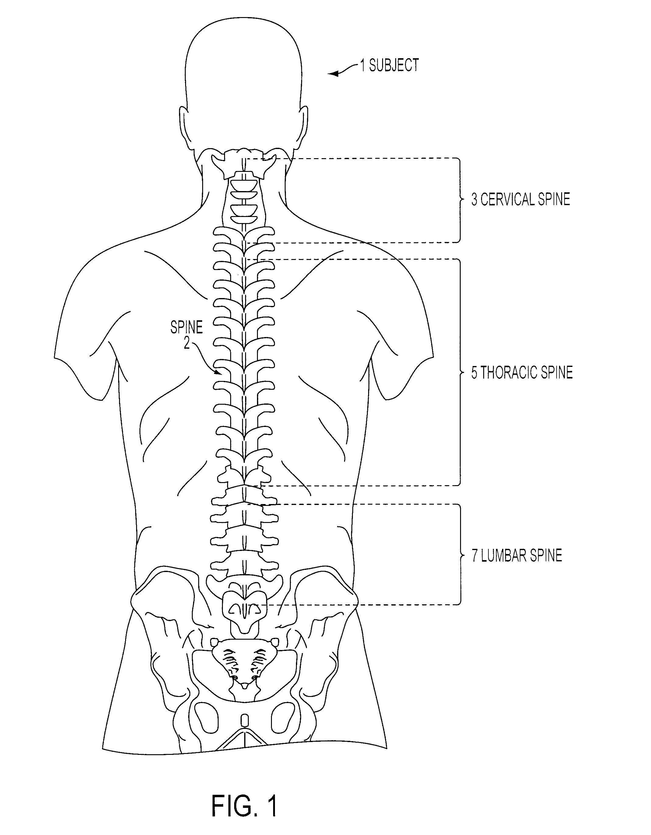
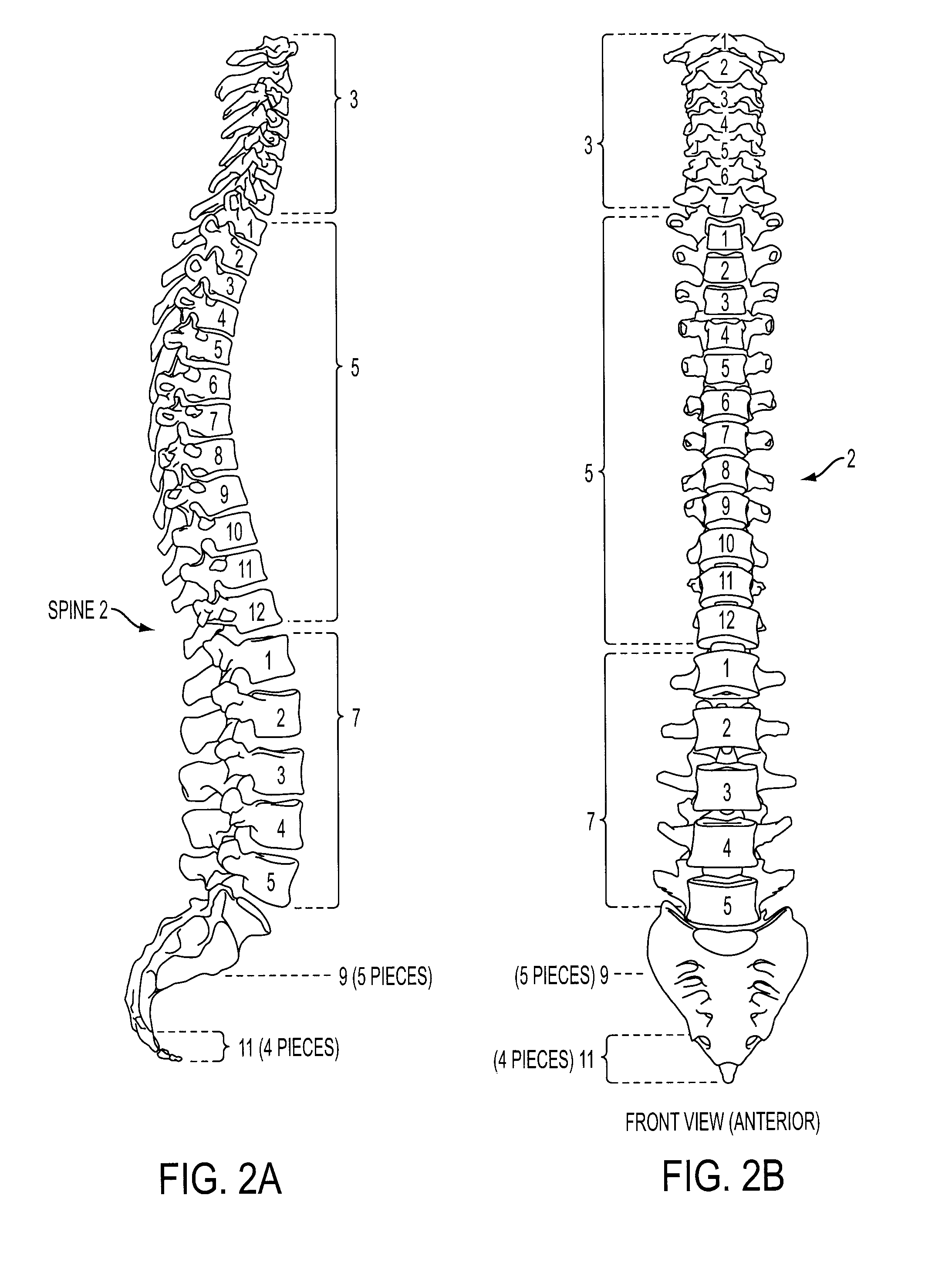
[0040]FIG. 1 illustrates a schematic posterior view of a spine 2 of a subject 1 and FIGS. 2A-B illustrate a schematic side view and posterior view of the spine 2, respectively. The normal anatomy of the spine of a human 1 is usually described by dividing up the spine 2 into three major sections: the cervical vertebrae 3, the thoracic vertebrae 5, and the lumbar vertebrae 7. Below the lumbar vertebrae 7 is a bone called the sacrum 9 and the coccyx 11, which is part of the pelvis. Each section is made up of individual bones called vertebrae 13. There are seven cervical vertebrae, twelve thoracic vertebrae, and five lumbar vertebrae.

[0041]FIGS. 3A-B illustrate a schematic plan view (axial overhead view) and side (lateral or elevation view) of a vertebra 13, respectively. FIG. 4 illustrates a schematic plan view (axial overhead view) of a vertebra 13. An individual vertebra 13 is made up of several parts. The vertabra consists of two stout rounded pedicles 15, one on each side which spr...


PUM

PropertyMeasurementUnit
heightaaaaaaaaaa
vertical heightaaaaaaaaaa

Abstract

A method and device for the insertion of a vertebral cage that may be done through a posterior approach that is minimally traumatic and does not require retraction of the spinal cord, dural sac or spinal nerves. The insertion of the cage may therefore be parallel to the spinal cord and the cage will be rotated ninety degrees (or as desired or required) in the vertebral body defect or as applicable to achieve its proper positioning before expansion.

Description

CROSS REFERENCE TO RELATED APPLICATIONS[0001]This application claims priority from U.S. Provisional Patent Application Ser. No. 60 / 878,894, filed on Jan. 5, 2007, entitled “Cement-filled Cage for Use in the Treatment of Spinal Tumors” and U.S. Provisional Application Ser. No. 60 / 904,502, filed Mar. 2, 2007 entitled “Cement-filled Cage for Use in the Treatment of Spinal Tumors,” the entire disclosures of which are hereby incorporated by reference herein in their entirety.BACKGROUND OF THE INVENTION[0002]Reconstruction of the anterior spine column may be necessary in conditions such as, but not limited thereto, fracture of the spine, tumors or infections of the spine. Conventional expandable cages for vertebral body replacement have been described to be inserted from the front of the spine. The conventional devices rely on, for example, a sort of mechanical device (ratchet type device or threaded expansion screw device) to achieve the expansion of the cage. Theses conventional cages a...

Claims


Application Information

Patent Timeline
Patent Type & Authority Applications(United States)
IPC IPC(8): A61F2/44A61B17/58
CPCA61B2017/0256A61F2/30742A61F2/44A61F2/441A61F2002/30476A61F2220/0025A61F2002/30583A61F2002/30601A61F2002/4685A61F2002/4692A61F2210/0085A61F2002/3055
Inventor ARLET, VINCENTPHAN, CHRISTOPHER U.
Owner UNIV OF VIRGINIA ALUMNI PATENTS FOUND
Why Eureka
Try Eureka