Method for repair of a spine and intervertebral implant

Inactive Publication Date: 2007-01-18
LIGNE
View PDF6 Cites 37 Cited by
  • Summary
  • Abstract
  • Description
  • Claims
  • Application Information

AI Technical Summary

Benefits of technology

[0027] This invention provides a method with appropriate implants and instruments that allow the surgeon to access the posterior elements, the anterior spine and deep spinal pathology while leaving the surrounding structures functionally intact. At the same time the method

Problems solved by technology

As the posterior spinal structures cover each other and tend to overlap, the ELIF Lateral Trajecto

Method used


Image

  • Method for repair of a spine and intervertebral implant
  • Method for repair of a spine and intervertebral implant
  • Method for repair of a spine and intervertebral implant

Examples


Embodiment Construction

[0035] Preferred embodiments of the invention are illustrated in the annexed drawings in which:

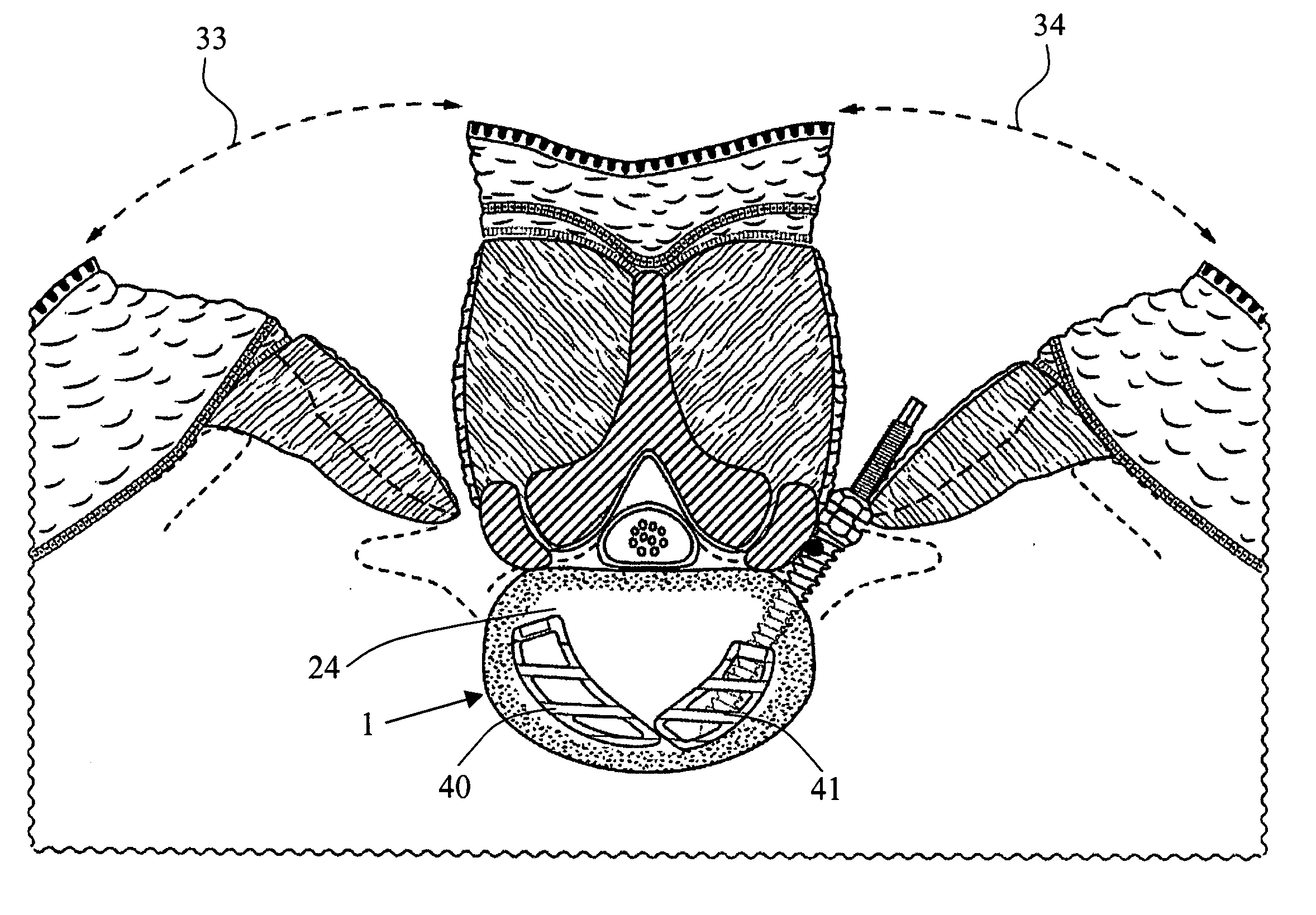
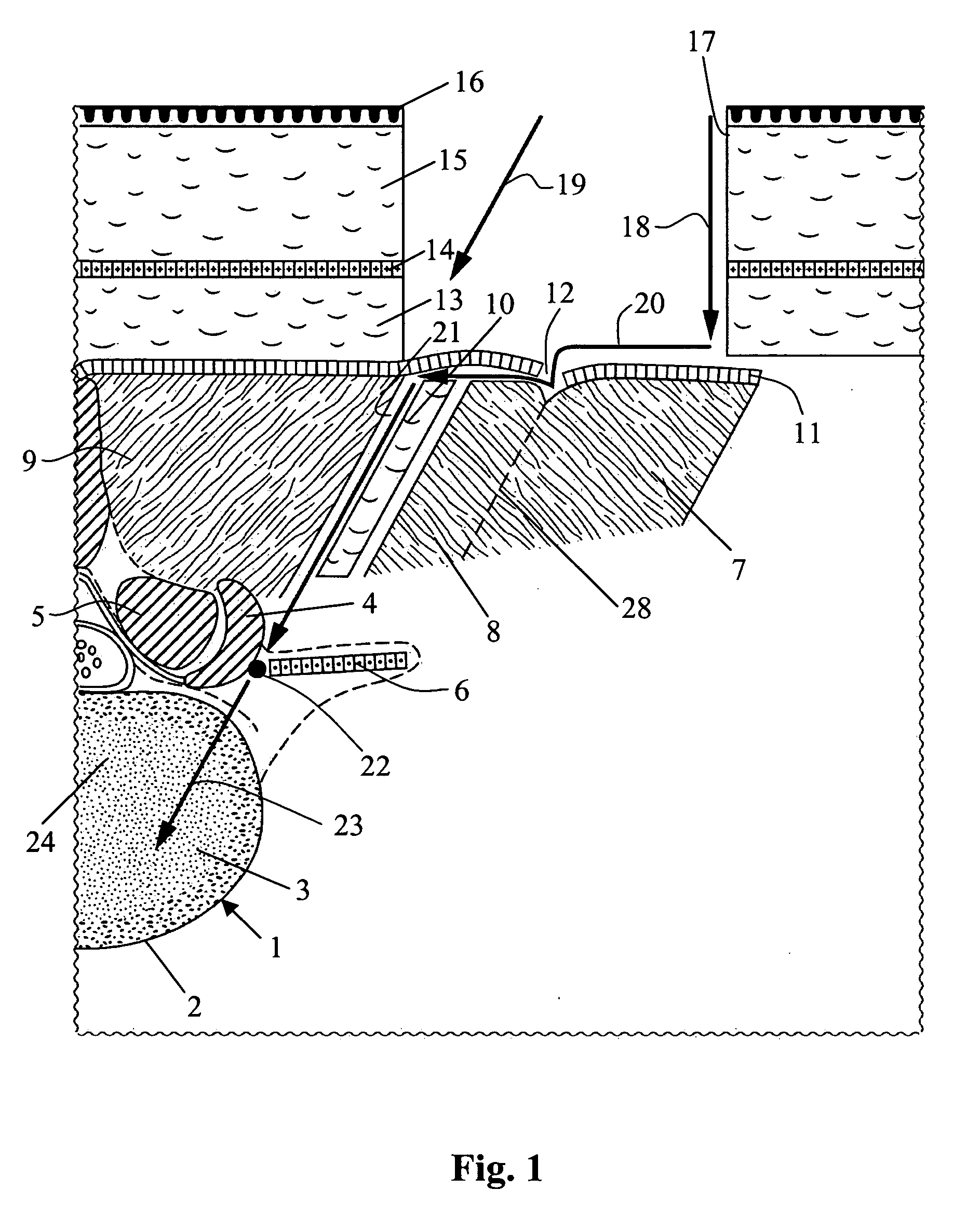
[0036]FIG. 1 illustrates surgical steps to enter the L4-L5 interdisc space;

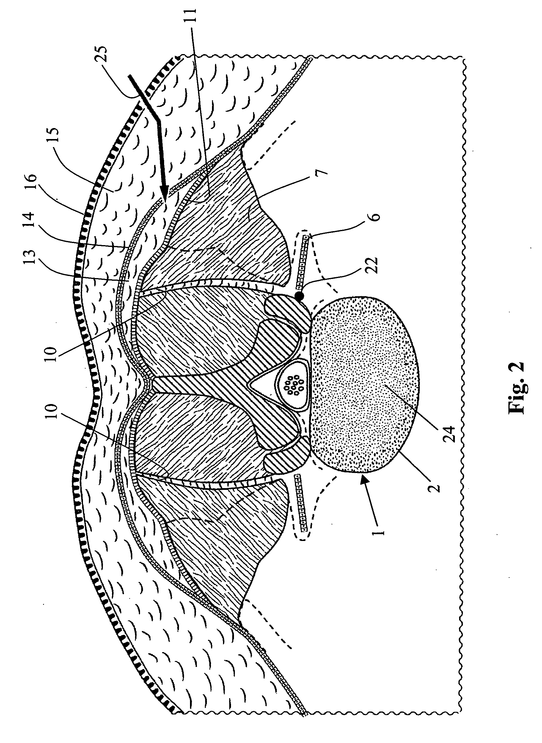
[0037]FIG. 2 a transverse section through the L4-L5 interdisc space and muscles on the posterior side of the spine, showing where the first incision is made through the skin, fat and the thorical lumbar fascia;

[0038]FIG. 3 a section according to FIG. 2, illustrating the steps of retracting the skin, fat and thorical lumbar fascia medial to the ELIF groove to find the interfascial boundry;

[0039]FIG. 4 a section according to FIG. 2 showing the steps of separating the ESA from the Longissimus Thoracis Pars Lumborum (LTPL) and separating the Multifidus from the LTPL using the interfascial boundary between the Multifidus and the LTPL;

[0040]FIG. 5 a section according to FIG. 2, illustrating a bilateral approach of the spine;

[0041]FIG. 6 a section according to FIG. 2, wherein a pedicle screw is placed;

[0042]FIG. 7 a...


PUM


Abstract

Repair of a spine from a posterior approach especially for locating an implant between a lower and upper human vertebra includes making an incision in the skin lateral to the midline, making an incision through the Erector Spinae Aponeurosis (ESA) following the ELIF groove, separating the ESA from the Longissimus Thoracis Pars Lumborum (LTPL), atraumatic separating the Multifidus from the LTPL using the interfascial boundary between the Multifidus and the LTPL, and creating a surgical plane having an angle of 20°-60°.

Description

BACKGROUND OF THE INVENTION [0001] The invention relates to a method for repair of a spine from a posterior approach especially for locating an implant between a lower and upper human vertebra. The invention further relates to an intervertebral implant and especially an implant for fusing together adjoining vertebrae bodies. [0002] Since its earliest history, surgery has been an imperfect compromise between the severity of the disease, the goal to cure, and the damage inflicted by the treatment. Spinal fusion surgery with implants is no different. The spine lies deep within the body. It is adjacent to vital structures that are easily damaged. To reach the spine and the pathology to be treated, many bodily structures are often disrupted or destroyed. Supporting bone of the vertebral column must at times be resected and stabilizing ligaments removed. Vessels providing blood supply are oftentimes cut and nerves can be severed. [0003] For certain patients, a lumbar spinal fusion procedu...

Claims


Application Information

Patent Timeline
IPC IPC(8): A61F2/44
CPCA61F2/30965A61F2/4455A61F2/4465A61F2002/4629A61F2002/4475A61F2002/448A61F2002/2835A61F2002/30593
Inventor RECOULES-ARCHE, DIDIERVELEZ, ROBERTLANGE, ROBERT
Owner LIGNE
Why Eureka
Try Eureka