Spinal implant

a spinal implant and module technology, applied in the field of modules of spinal implants, can solve the problems of affecting the function of spinal implants, so as to achieve less scarring, less invasiveness, and convenient removal

Inactive Publication Date: 2008-02-14
ZIMMER SPINE INC +1
View PDF16 Cites 41 Cited by
  • Summary
  • Abstract
  • Description
  • Claims
  • Application Information

AI Technical Summary

Benefits of technology

[0012]This invention has a number of advantages. First, the spinal implant of this invention is configured for insertion using a posterior approach during surgery. Relative to a typical surgery using an anterior approach, the present invention is substantially less invasive and will have less scarring. Secondly, the spinal implant mimics a healthy disc in that the implant is viscoelastic, thus enabling the spine to bend in a more normal fashion than a typical implant made from metals. In addition, the implant of this invention is relatively easy to remove if it needs to be replaced, and through practice of this invention, exit strategies are conserved. The modular implant of this invention is easier to remove than a one-piece elastomeric implant that is formed in site or which is introduced via an anterior approach. Likewise, implants positioned via an anterior approach frequently have substantial bone ingrowth that results in the need for cutting away bone if the implant is replaced, which cutting is obviated in the practice of this invention.

Problems solved by technology

Such invasive surgery may cause substantial scarring.
Such polymeric-based devices are also inserted through an anterior approach, which may lead to scarring.
Removal of prior devices can be complicated by ingrowth of bone, leading to potential cutting of vertebrae in order to remove an implant if it requires replacement.

Method used


Image

  • Spinal implant
  • Spinal implant
  • Spinal implant

Examples


Embodiment Construction

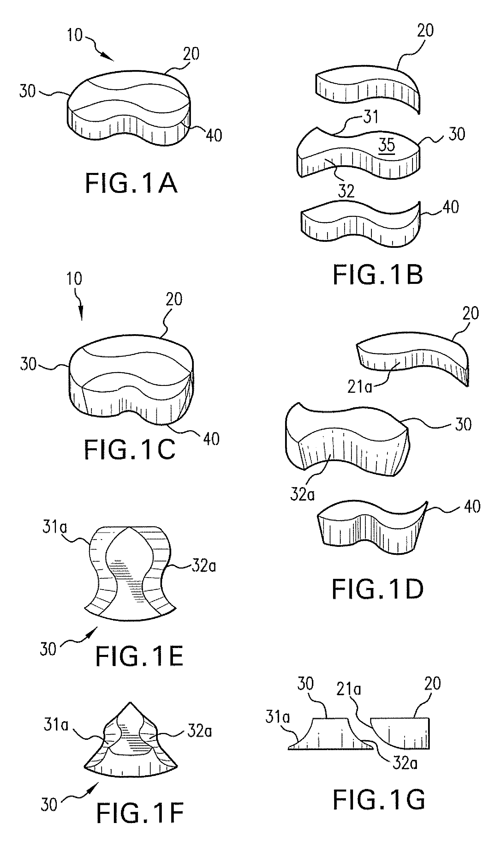
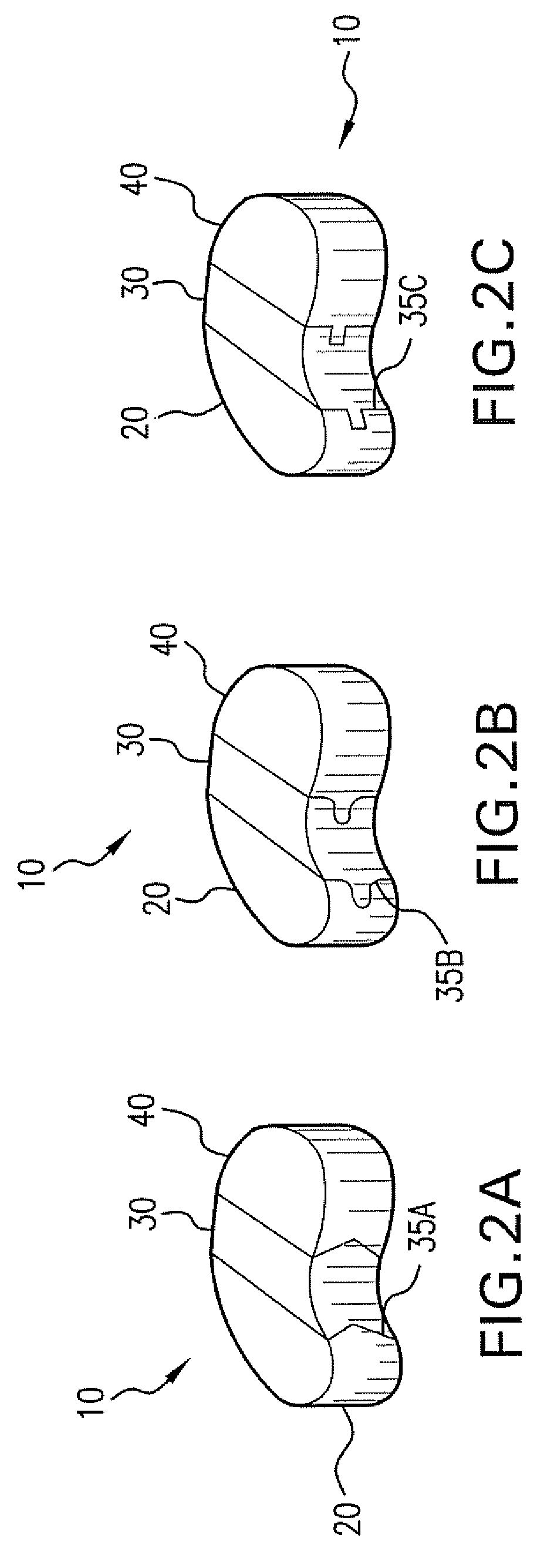
[0023]FIGS. 1A and 1B show one embodiment of the spinal implant of this invention. The implant 10 is composed of a first component 20, a second component 30, an a third component 40. Together the components form an implant 10 that is configured and sized to fit into a given spinal disc. The implant 10 is sized according to the disc where the implant is to be inserted. It should be appreciated that the components compliment one another, and when placed in the disc abut one another. In FIGS. 1A and 1B, the sides 31, 32 of the second component 30 are perpendicular to the face 35. The sides of the first component 20 and the third component 40 are similarly perpendicular to their respective faces. In FIGS. 1A and 1B, the second component 30 has a “fish” shaped face 35, with the components together forming an implant 10. The implant 10 can be configured with the sides of each component pointing in different directions depending on whether the implant is inserted via a posterior approach, ...


PUM

PropertyMeasurementUnit
heightaaaaaaaaaa
shapeaaaaaaaaaa
elasticaaaaaaaaaa

Abstract

A spinal implant that includes a plurality of components adapted for use as an implant in a disc. Each component is configured to be inserted into a void of a disc and each component complimentarily abuts at least one other component to form the implant. A method treating a spinal disc that includes creating a port from a posterior approach into the disc space of a spinal disc; and inserting components that form a spinal implant into the disc space through the port to form the spinal implant. A method of forming a modular spinal implant, comprising: preparing a plurality of components that are shaped for insertion into a disc, wherein each component abuts at least one other component in the disc.

Description

FIELD OF THE INVENTION[0001]This invention concerns a modular spinal implant for posterior insertion that includes a plurality of components made from an elastic material.BACKGROUND OF THE INVENTION[0002]Spinal implants are frequently rigid and are surgically implanted by an anterior approach. Such invasive surgery may cause substantial scarring. Spinal implants have been proposed that are polymeric materials, setting up either in the disc space or presented as a monolithic structure. Such polymeric-based devices are also inserted through an anterior approach, which may lead to scarring.[0003]Removal of prior devices can be complicated by ingrowth of bone, leading to potential cutting of vertebrae in order to remove an implant if it requires replacement.[0004]The inventors have recognized that a need exists for a spinal implant that can be introduced into a disc space, such as after discectomy, through a minimally invasive posterior approach and that alleviates the prior problems di...

Claims


Application Information

Patent Timeline
Patent Type & Authority Applications(United States)
IPC IPC(8): A61F2/44
CPCA61B17/842A61F2250/0018A61F2/442A61F2002/30014A61F2002/30065A61F2002/30069A61F2002/30075A61F2002/30383A61F2002/30462A61F2002/30471A61F2002/30563A61F2002/30604A61F2002/30677A61F2002/30909A61F2002/30971A61F2002/444A61F2002/448A61F2002/4677A61F2210/0061A61F2210/0071A61F2220/0025A61F2220/0075A61F2220/0091A61F2/441
Inventor BERGERON, BRIAN J.
Owner ZIMMER SPINE INC
Why Eureka
Try Eureka