Fixation device and method

a technology of fixation device and fixation device, which is applied in the field of fixation device and method, can solve the problems of disc degeneration, pain and other complications, degeneration of spinal disc, etc., and achieve the effects of less invasiveness, less soft tissue, and improved anchoring within the join

Inactive Publication Date: 2013-09-17
STOUT MEDICAL GROUP
View PDF556 Cites 111 Cited by
  • Summary
  • Abstract
  • Description
  • Claims
  • Application Information

AI Technical Summary

Benefits of technology

[0010]The device can be less invasive than typical existing devices. For example, the device can be in a compacted (i.e., small) configuration when inserted into a patient and transformed into an expanded (i.e., large) configuration when positioned at the target site. For example, the device can be expanded when the device is between the inferior and superior vertebral body surfaces. The device can create less soft tissue (e.g., bone) disruption than a typical fusion system. The device in an expanded configuration can improve anchoring within the joint, structural stability, and create an environment for bone healing and growth leading to fusion between adjacent vertebrae.

Problems solved by technology

Other ailments of the spine result in degeneration of the spinal disc in the intervertebral space between the vertebral bodies.
In either case, disc degeneration can cause pain and other complications.
This can relieve pain in the short term, but also often increases the risk of long-term problems and can result in motor and sensory deficiencies resulting from the surgery.

Method used


Image

  • Fixation device and method
  • Fixation device and method
  • Fixation device and method

Examples


Embodiment Construction

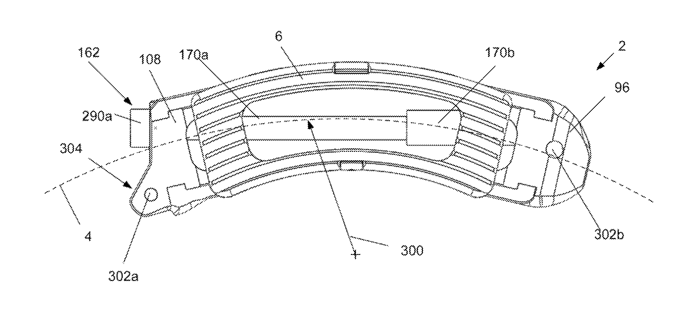
[0051]A device 2 is disclosed that can be inserted into a target site 264 with the device 2 in a compressed or contracted (i.e., small) configuration. Once positioned in the deployment site, the device 2 can be transformed into an expanded (i.e., larger, bigger) configuration. The device 2 can be inserted and expanded in orthopedic target sites 264 for fixation and / or support. For example, the device 2 can be inserted and expanded over a guidewire between adjacent vertebral bodies.

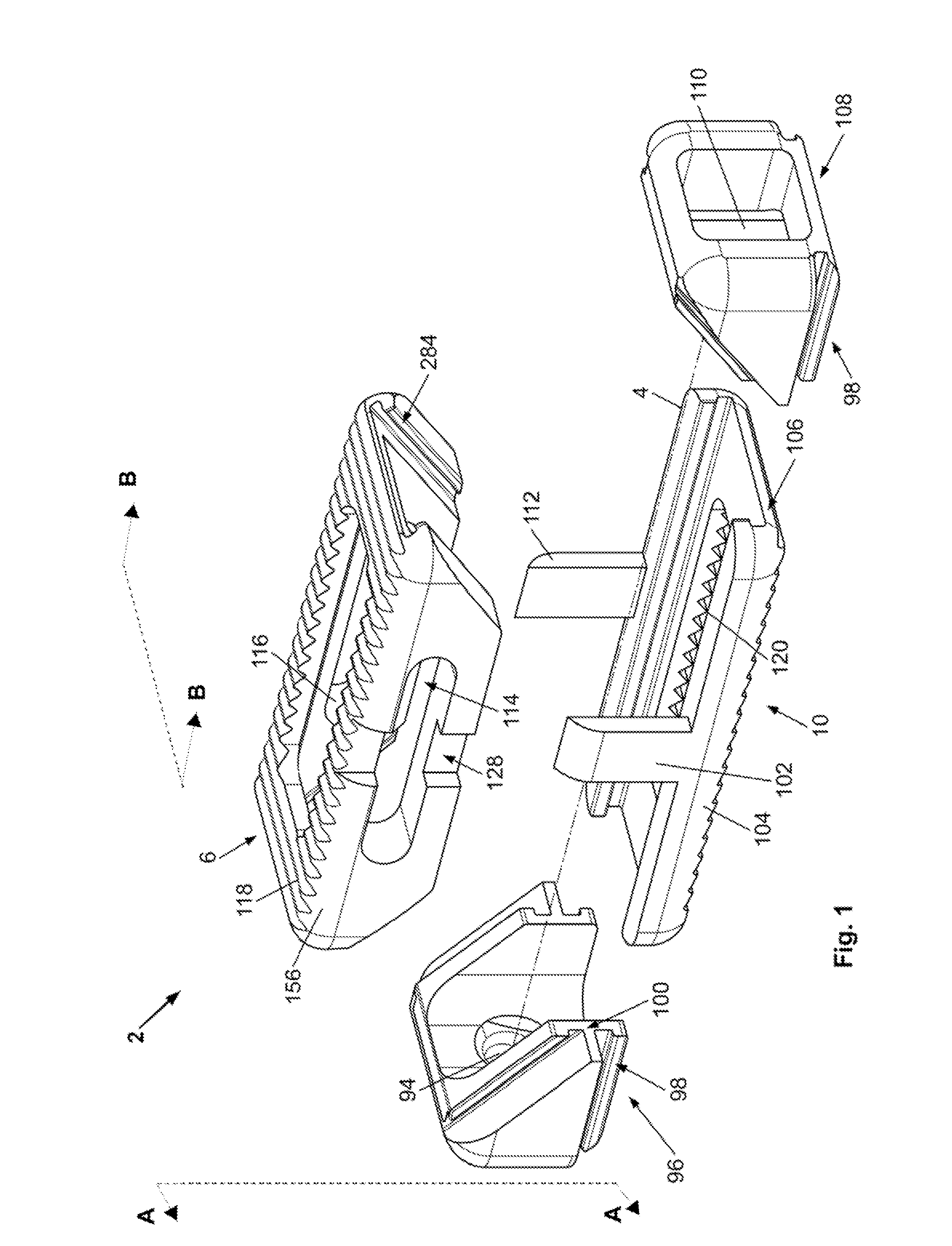
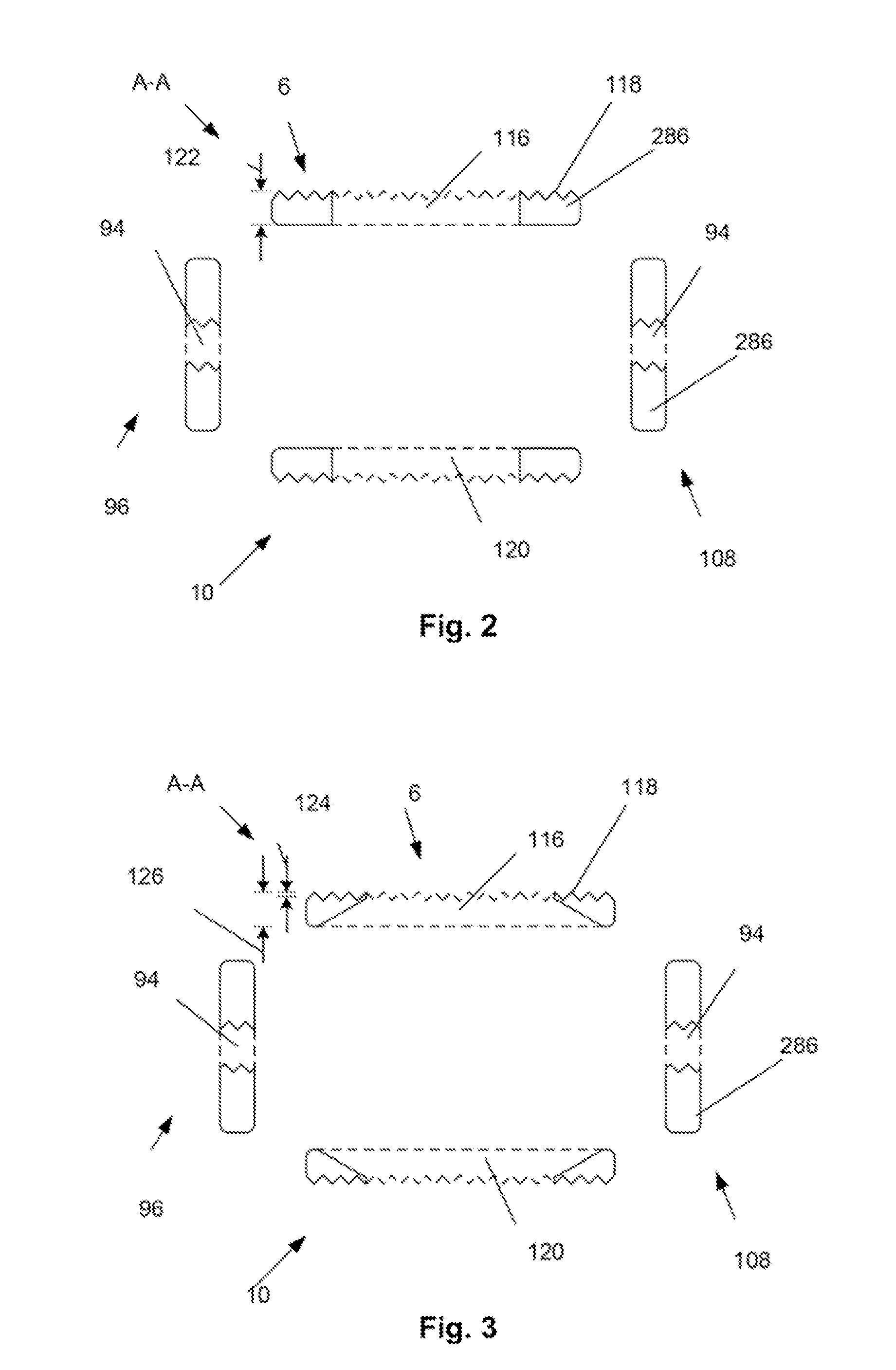
[0052]FIG. 1 illustrates that the device 2 can have a first longitudinal end and a second longitudinal end along a longitudinal axis 4. The longitudinal axis 4 can be straight or substantially straight. The device 2 can have a bottom or plate 286 (bottom and base plate are used interchangeably) and a top plate 6. The base 138 or bottom plate 10 and top plate 6 can be or have plates 286, panels, struts 216 (e.g., legs), ports, cells 88, and combinations thereof. The base plate 10 and top plate 6 can be conf...


PUM


Abstract

An implantable orthopedic stability device is disclosed. The device can have a contracted and an expanded configuration. A method of using the device between adjacent vertebral body surfaces surfaces for support and / or fixation of either or both of the adjacent vertebrae is also disclosed.

Description

BACKGROUND OF THE INVENTION[0001]1. Technical Field[0002]Devices and methods for fixation of tissue are disclosed. More specifically, the devices and methods can be for inter body vertebral fusion of vertebrae or fusion of other bones to one another.[0003]2. Background of the Art[0004]A vertebroplasty device and method that eliminates or reduces the risks and complexity of the existing art is desired. A vertebroplasty device and method that may reduce or eliminate the need to inject a liquid directly into the compression fracture zone is also desired.[0005]Other ailments of the spine result in degeneration of the spinal disc in the intervertebral space between the vertebral bodies. These include degenerative disc disease and traumatic injuries. In either case, disc degeneration can cause pain and other complications. Conservative treatment can include non-operative treatment requiring patients to adjust their lifestyles and submit to pain relievers and a level of underlying pain. Op...

Claims


Application Information

Patent Timeline
Patent Type & Authority Patents(United States)
IPC IPC(8): A61F2/44
CPCA61B17/8858A61F2/4425A61F2/447A61F2002/3008A61F2002/30242A61F2002/30387A61F2002/30448A61F2002/30492A61F2002/30507A61F2002/30515A61F2002/3052A61F2002/30523A61F2002/3055A61F2002/30578A61F2002/30777A61F2002/30779A61F2002/30825A61F2002/30904A61F2002/443A61F2002/4475A61F2002/4629A61F2002/4677A61F2220/0025A61F2220/005A61F2002/30593
Inventor GREENHALGH, E. SKOTTROMANO, JOHN-PAUL
Owner STOUT MEDICAL GROUP
Why Eureka
Try Eureka