Endovascular splinting devices and methods

a splinting device and endovascular technology, applied in the field of endovascular splinting devices and methods, can solve the problems of heart failure, significant increase in wall tension and/or stress, and dilatation of the left ventricular chamber, so as to achieve less invasiveness, less risk to the patient, and more clinical utility.

Inactive Publication Date: 2007-03-08
EDWARDS LIFESCIENCES LLC
View PDF99 Cites 120 Cited by
  • Summary
  • Abstract
  • Description
  • Claims
  • Application Information

AI Technical Summary

Benefits of technology

[0010] Due to the drawbacks and limitations of the previous devices and techniques for treating a failing heart, including such a heart having dilated, infarcted, and / or aneurysmal tissue, there exists a need for alternative methods and devices that are less invasive and pose less risk to the patient, both after and during placement, and are likely to possess more clinical utility.

Problems solved by technology

Typically these processes result in dilatation of the left ventricular chamber.
With damage to the myocardium or chronic volume overload, however, there are increased ill requirements put on the contracting myocardium to such a level that this compensated state is never achieved and the heart continues to dilate.
One problem with a large dilated left ventricle is that there is a significant increase in wall tension and / or stress both during diastolic filling and during systolic contraction.
However, in a failing heart, the ongoing dilatation is greater than the hypertrophy and the result is a rising wall tension requirement for systolic contraction.
This is felt to be an ongoing insult, to the muscle myocyte resulting in further muscle damage.
Additionally, because of the lack of cardiac output, a rise in ventricular filling pressure generally results from several physiologic mechanisms.
Geometric abnormalities resulting from a dilated left ventricle may cause or exacerbate improper functioning of the mitral valve, including mitral valve regurgitation, i by altering the normal position and dimension of the valve, particularly the valve annulus.
These drug therapies offer some beneficial effects but do not stop the progression of the disease.

Method used


Image

  • Endovascular splinting devices and methods
  • Endovascular splinting devices and methods
  • Endovascular splinting devices and methods

Examples


Embodiment Construction

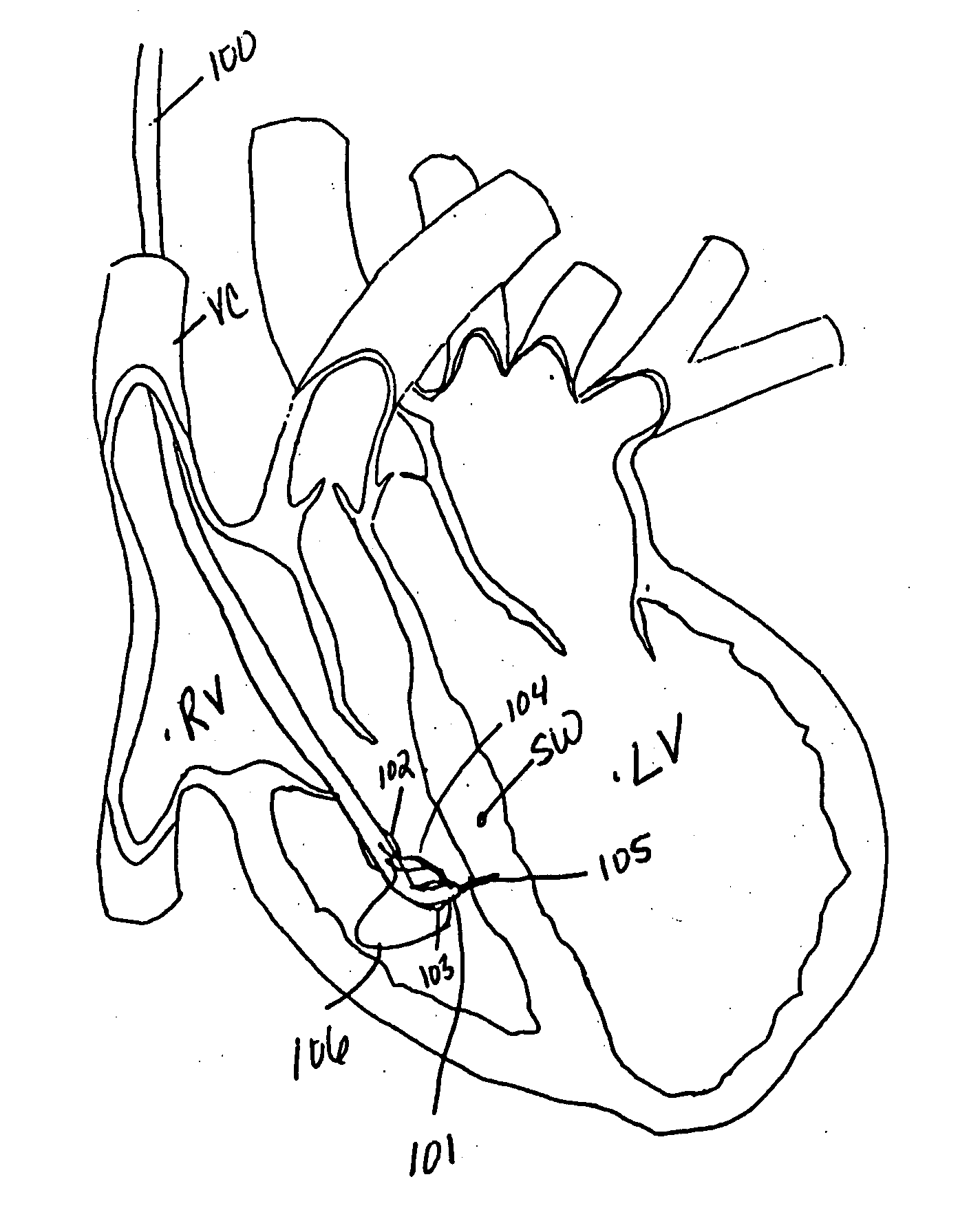
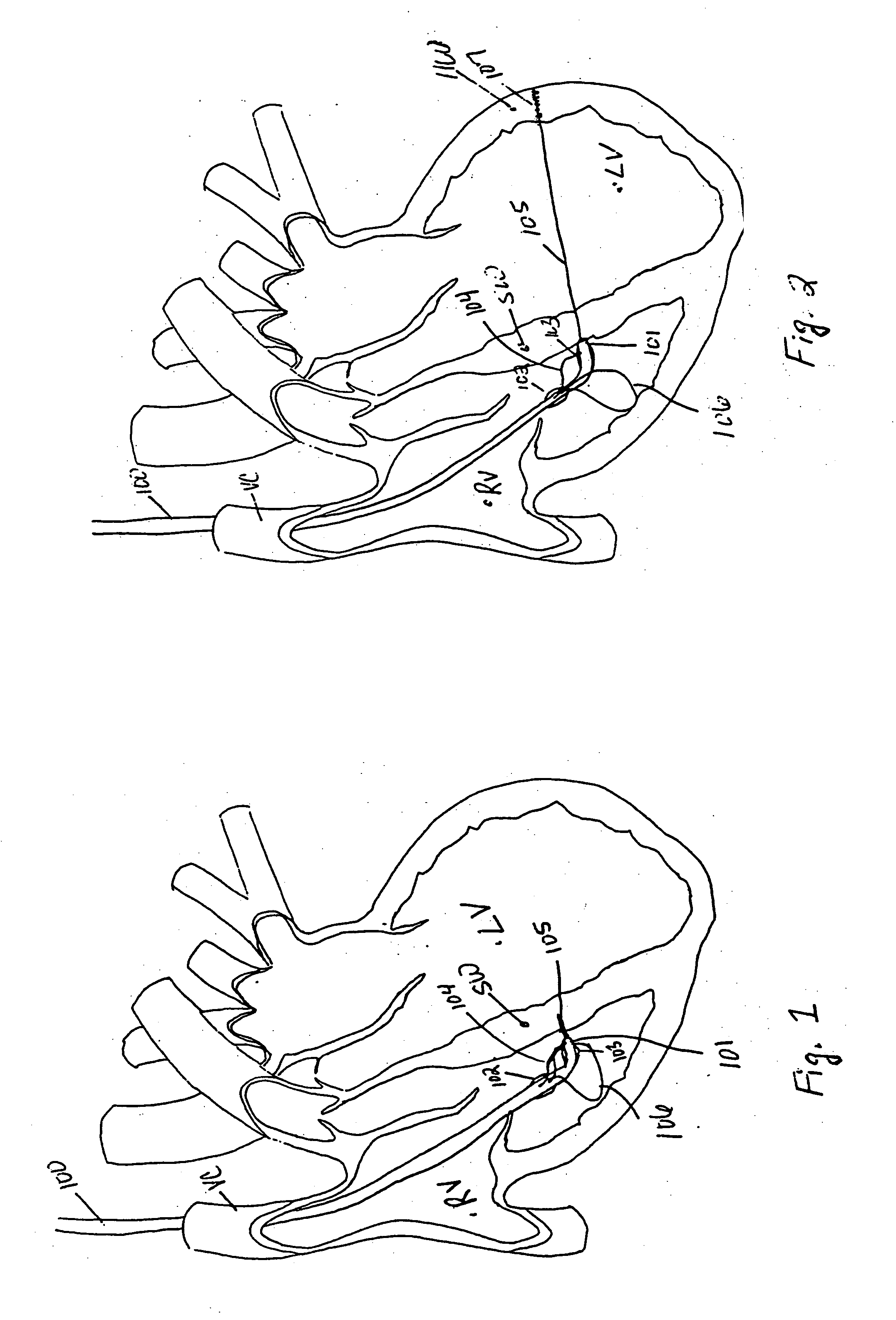
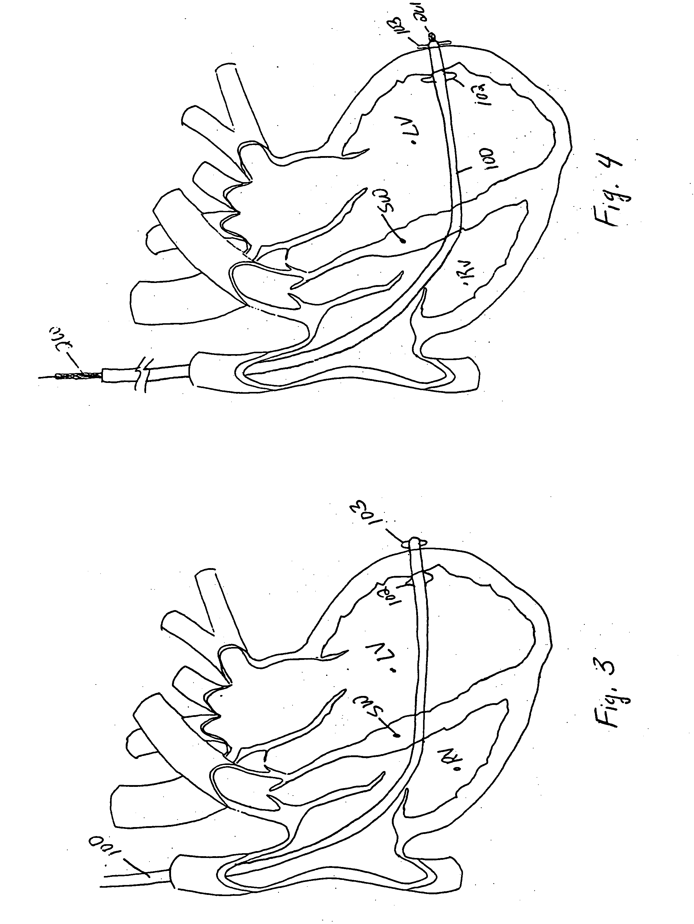
[0058] The various aspects of the invention to be discussed herein generally pertain to devices and methods for treating heart conditions, including, for example, dilatation, valve incompetencies, including mitral valve leakage, and other similar heart failure conditions. Each device of the present invention preferably operates passively in that, once placed in the heart, it does not require an active stimulus, either mechanical, electrical, or otherwise, to function. Implanting one or more of these devices alters the shape or geometry of the heart, both locally and globally, and thereby increases the heart's efficiency. That is, the heart experiences an increased pumping efficiency through an alteration in its shape or geometry and concomitant reduction in stress on the heart walls. In addition, the devices of the present invention may operate to assist in the apposition of heart valve leaflets to improve valve function.

[0059] The inventive devices and related methods offer numero...


PUM


Abstract

A method for placing a splint assembly transverse a heart chamber includes providing an elongate member having a first end and a second end and a deployable heart-engaging assembly connected to at least the first end. The method includes advancing the elongate member through vasculature structure and into the heart chamber such that the first end of the elongate member extends through a first location of a wall surrounding the heart chamber and the second end extends through a second location of the heart chamber wall substantially opposite the first location. A deployable heart-engaging assembly is deployed such that it engages with a first exterior surface portion of the heart chamber wall adjacent the first location. The elongate member is secured with respect to the heart with a second heart-engaging assembly connected to the second end. The second heart-engaging assembly engages with a second exterior surface portion of the heart chamber wall adjacent the second location. A splint assembly includes an expandable heart-engaging assembly formed partially from portions forming the elongate member of the splint assembly. A delivery tool includes a tubular member configured to be advanced through vasculature structure and has a curved distal end.

Description

FIELD OF THE INVENTION [0001] The present invention pertains to devices for treating a failing heart and related methods for placing the devices. In particular, the invention pertains to splinting devices placed on the heart to reduce the radius of curvature and / or alter the geometry or shape of the heart to thereby reduce wall stress in the heart and improve the heart's pumping performance. The devices and methods of the present invention are directed toward endovascular techniques used to facilitate placement of the splinting devices on the heart. BACKGROUND OF THE INVENTION [0002] Heart failure is a common outcome in the progression of many forms of heart disease. Heart failure may be considered as the condition in which an abnormality of cardiac function is responsible for the inability of the heart to pump blood at a rate commensurate with the requirements of the metabolizing tissues, or can do so only at an abnormally elevated filling pressure. There are many specific disease ...

Claims


Application Information

Patent Timeline
Patent Type & Authority Applications(United States)
IPC IPC(8): A61B17/08A61B17/00A61B17/04A61B17/064A61B17/068A61B19/00
CPCA61B17/00234A61F2/2487A61B17/0682A61B19/54A61B2017/00243A61B2017/003A61B2017/00557A61B2017/00907A61B2017/0404A61B2017/0409A61B2017/0412A61B2017/0437A61B2017/0464A61B2017/048A61B2017/0496A61B17/064A61B90/39
Inventor VIDLUND, ROBERT M.SIMMON, MARC A.MORTIER, TODD J.SCHWEICH, CYRIL J. JR.KEITH, PETER T.SCHROEDER, RICHARD F.KALGREEN, JASON
Owner EDWARDS LIFESCIENCES LLC
Why Eureka
Try Eureka