Lockout mechanism for a surgical stapler

a locking mechanism and stapler technology, applied in the field of surgical staplers, can solve the problems of complicated knife holding mechanism, patient could be severely harmed, life put in danger,

Inactive Publication Date: 2010-03-18
FRANKENMAN INT
View PDF6 Cites 912 Cited by
  • Summary
  • Abstract
  • Description
  • Claims
  • Application Information

AI Technical Summary

Benefits of technology

[0025]In a further preferred embodiment of the staple cartridge, longitudinal movement of said cutting means in the distal direction causes the distal end of said cutting means to contact a portion of said release member. Upon further movement of said cutting means in the distal direction, said release member is plastically bent with respect to said body of said staple cartridge and thus said blocking member is released. When said cutting means returns to its initial position, said bia

Problems solved by technology

Otherwise the patient could be severely harmed by leakage of fluids from the resected organ and his life put in danger.
Allowing the knife to move in a direction other

Method used


Image

  • Lockout mechanism for a surgical stapler
  • Lockout mechanism for a surgical stapler
  • Lockout mechanism for a surgical stapler

Examples


first embodiment

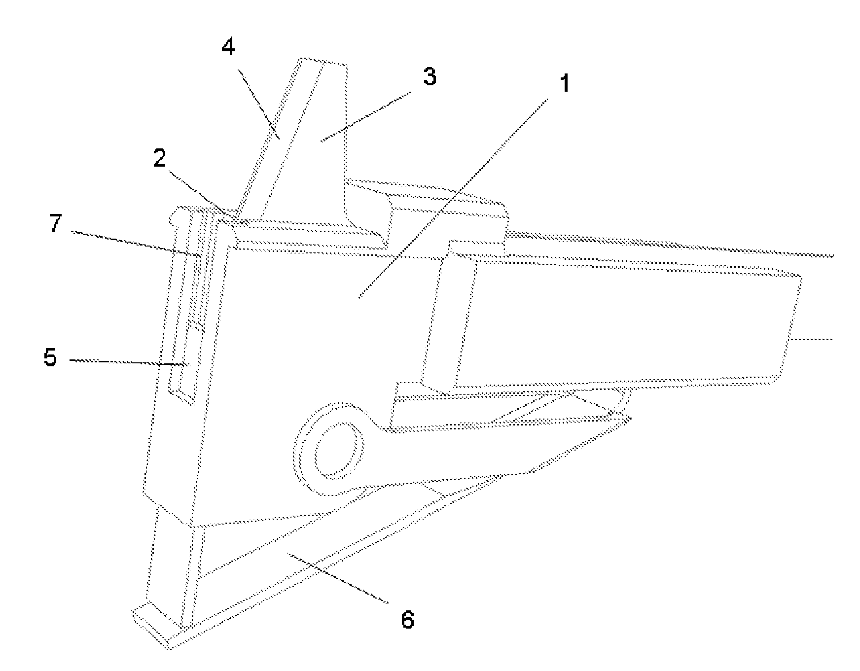
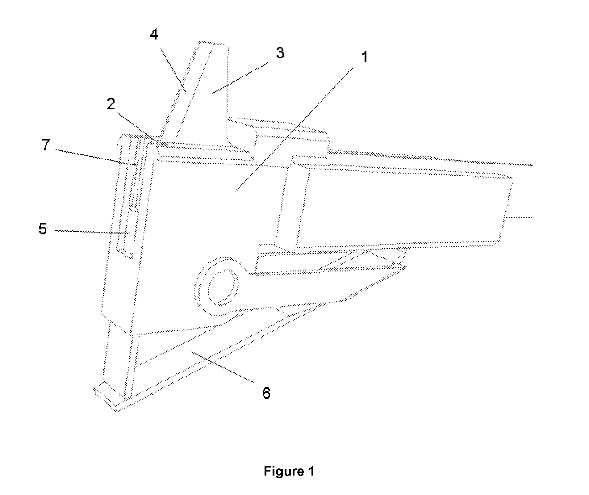
[0046]In FIG. 1 a perspective view of a lockout mechanism of a surgical stapler according to the present invention is depicted. For purpose of clarity, only the guiding element 1, the cutting means 3, and the lockout mechanism of the surgical stapler are shown. The guiding element 1 provides a guiding channel 2 having dimensions adapted to the dimensions of the cutting means 3 for ensuring a secure guiding of the cutting means 3. The cutting means 3 comprises a blade 4 at its distal end. The lockout mechanism comprises a blocking member 5 and a biasing member 6. In this embodiment of the present invention, the blocking member 5 is an essentially planar element. For guiding the blocking member 5, the guiding element 1 provides a passage 7 extending essentially perpendicular to the guiding channel 2. Within the passage 7, the blocking member 5 is movable from a first position into a second position and vice versa. In FIG. 1, the blocking member 5 is shown in the second position. In th...

second embodiment

[0051]FIG. 6 illustrates a perspective view of a lockout mechanism of a surgical stapler according to the present invention. This embodiment is similar to that described above except that the blocking member 5 and the biasing member 6 are replaced by a single piece of wire 5, 6 with spring-like properties. The wire 5, 6 is shown mounted in the guiding element 1 and obstructing advancement of the cutting means 3. Other than these differences, this embodiment operates in a very similar manner, as is depicted in FIGS. 7-9.

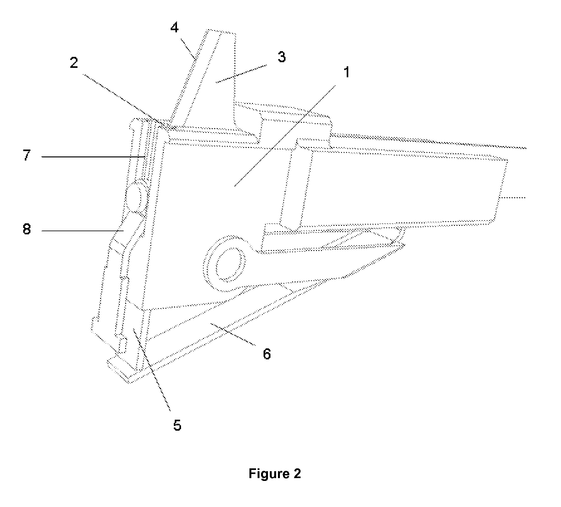
[0052]FIG. 7 illustrates a section view through the lockout mechanism according to FIG. 6 being engaged by a release member 8 of a staple cartridge 9 according to the second embodiment of the present invention. The wire 5 is shown captured by the release member 8 and retained in the second position, in which the wire 5 permits longitudinal movement of the cutting means 3. The release member 8 is moulded integrally with the body of the staple cartridge 9. In the depict...

third embodiment

[0055]FIG. 10 illustrates a perspective view of the cutting means 3 and the release member 8 according to the present invention wherein the release member 8 is formed as a separate component. By forming the release member 8 as a separate component, the injection moulding of the staple cartridge does not need to be modified, which would incur large costs. The figure depicts the cutting means 3 positioned relative to the release member 8 prior to, and on completion of, operation of the surgical stapler. The other components are omitted for purpose of clarity. The release member 8 is preferably made from a steel stamping. For engaging the blocking member, not shown in this figure, the release member 8 comprises a button riveted into sheet. By conditioning the sheet to a malleable temper, the release member 8 may bend plastically without breaking.

[0056]FIG. 11 illustrates a perspective view of the components according to FIG. 10 including the lockout mechanism. In this third embodiment,...


PUM


Abstract

The invention relates to a surgical stapler for applying at least two rows of staples, said surgical stapler comprising a cartridge housing said rows of staples and having a slot extending along the cartridge between two rows of staples, said surgical stapler further comprising a cutting means movable along said slot and a lockout mechanism for preventing movement of said cutting means, wherein said lockout mechanism comprises a blocking member movable between a first position, in which the blocking member blocks movement of said cutting means, and a second position, in which the blocking member permits movement of said cutting means, and a biasing member for biasing said blocking member towards said first position and wherein said cartridge comprises a release member for moving said blocking member towards said second position upon insertion of said cartridge into said surgical stapler.

Description

CROSS-REFERENCE TO RELATED APPLICATIONS[0001]This application claims the priority of European Patent Application No.: 08 105 350.6 filed 15 Sep. 2008, pursuant to 35 U.S.C. 119(a)-(d), the contents of which is incorporated herein by reference in its entirety as if fully set forth herein.FIELD OF INVENTION[0002]The invention relates to a surgical stapler for applying a plurality of surgical staples in rows and for cutting the stapled tissue between two of the staple rows. In particular, the invention relates to an improved lockout feature for a surgical stapler preventing the stapler to be used without staples.BACKGROUND OF INVENTION[0003]Surgical staplers are well known medical tools especially for closure of wounds but also for closure of internal organs prior to transection or resection. Surgical staplers often are used with removable and disposable cartridges housing the staples in essentially parallel rows and having a slot between two of these rows for guiding a knife. The surg...

Claims


Application Information

Patent Timeline
IPC IPC(8): A61B17/072
CPCA61B17/068A61B2019/4873A61B2017/07285A61B17/07207A61B2090/0814
Inventor WENG, ZHIQIANG
Owner FRANKENMAN INT
Why Eureka
Try Eureka