

In-vehicle manipulation apparatus and in-vehicle input apparatus
- Summary
- Abstract
- Description
- Claims
- Application Information
AI Technical Summary
Benefits of technology
Problems solved by technology
Method used
Image

Examples
first embodiment
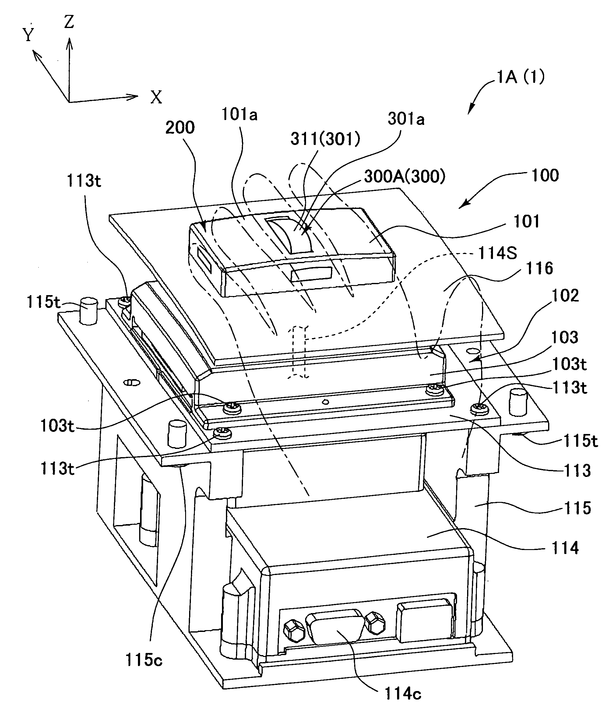
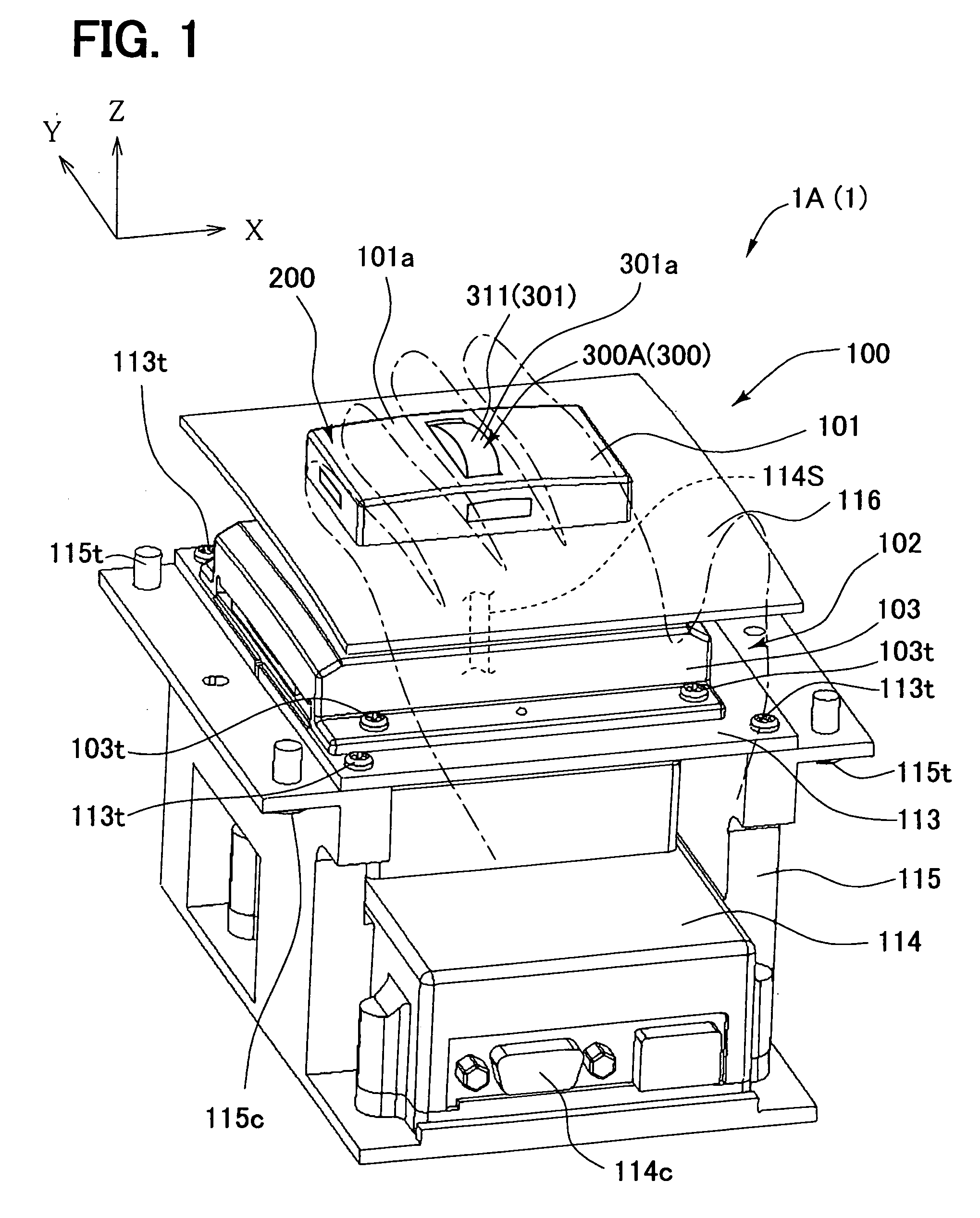
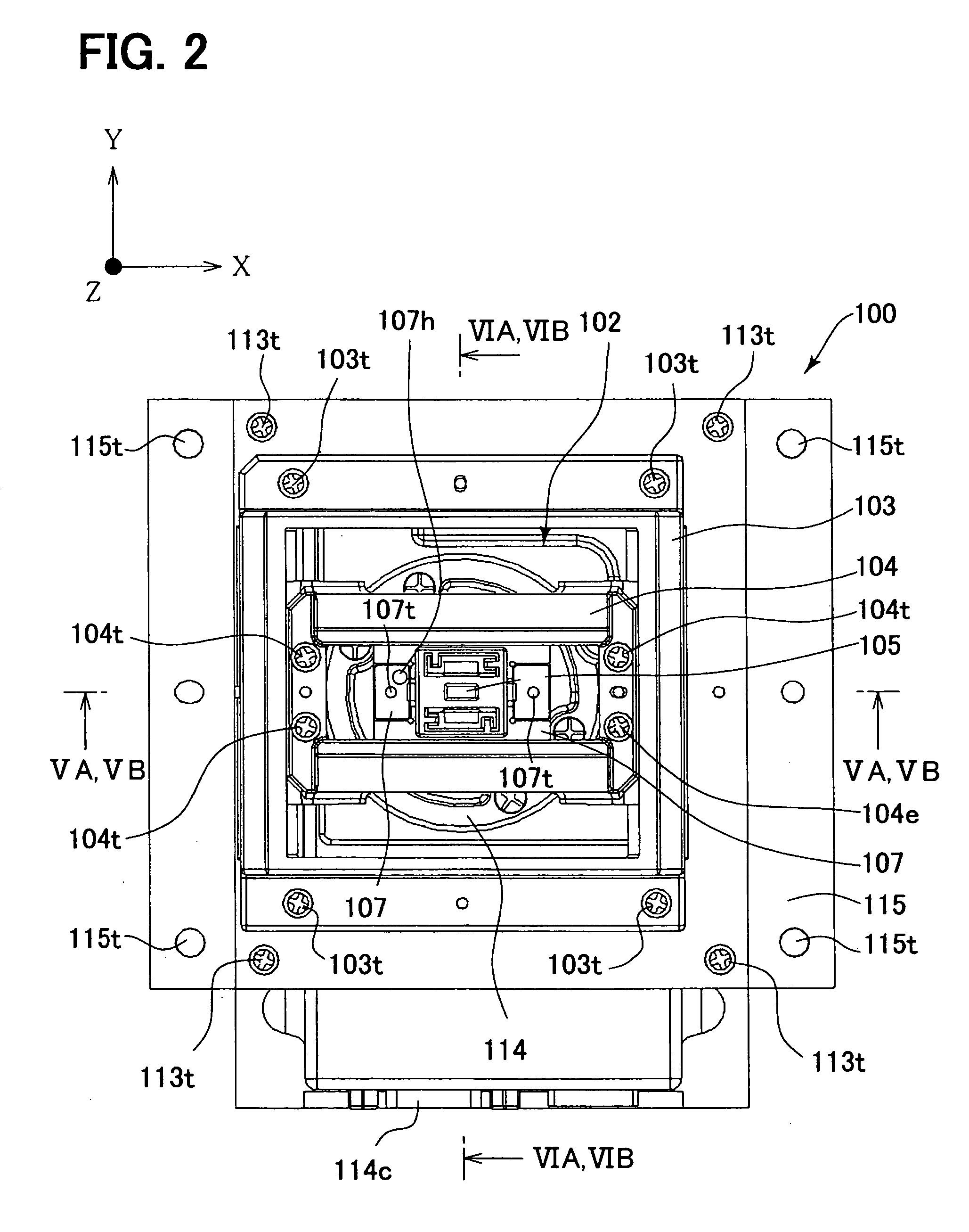
[0074]FIG. 1 is a perspective view showing an operational structure portion (body) of an in-vehicle manipulation apparatus, and FIG. 2 is a plan view of a body 100 in a state where a movable operation section 101 is removed. The in-vehicle manipulation apparatus 1A(1) is fixed to a side of a driver seat DS in a center console C in an interior of a car as shown in FIG. 37, and may be operated by a user in either of the driver seat DS and a passenger seat PS. While a use object of the in-vehicle manipulation apparatus 1A(1) is not particularly limited, for example, the manipulation apparatus is used for operation (display position movement operation) of moving, on the screen, a display position of a beforehand determined display object being displayed on the screen while viewing a screen of a monitor (display device) 51 provided in a center console. The in-vehicle manipulation apparatus 1A(1) is used for operation (position specifying input) for performing position specifying input of...
second embodiment
[0142]A second embodiment is described using FIGS. 17 to 21.
[0143]FIG. 17 is a perspective view showing an operational structure portion (body) of an in-vehicle manipulation apparatus of the second embodiment, FIG. 18 is an exploded perspective view of a movable operation section thereof, FIGS. 19A, 19B are section views along XIXA-XIXA and along XIXB-XIXB in FIG. 17 (sections as those of FIGS. 5A, 5B), FIGS. 20A, 20B are section views along XXA-XXA and along XXB-XXB in FIG. 17 (sections as those of FIGS. 6A, 6B), and FIG. 21 is a block diagram showing a general configuration concept of the manipulation apparatus of FIG. 17.
[0144]The in-vehicle manipulation apparatus 1B(1) of the second embodiment has a touchpad operation section 300B as a one-dimensional operation section 300. The touchpad operation section 300B has a touch panel 321 on an end surface side of a movable operation section 101 of a two-dimensional operation section 200 in such a manner that a touch operation surface b...
third embodiment
[0166]A third embodiment is described using FIGS. 23 to 27.
[0167]FIG. 23 is a perspective view showing an operational structure portion (body) of an in-vehicle manipulation apparatus of the third embodiment, FIG. 24 is an exploded perspective view of a movable operation section thereof, FIGS. 25A, 25B are section views along A-A in FIG. 23 (sections as those of FIGS. 5A, 5B), FIGS. 26A, 26B are section views along B-B in FIG. 23 (sections as those of FIGS. 6A, 6B), and FIG. 27 is a block diagram showing a general configuration concept of the manipulation apparatus of FIG. 23.
[0168]The in-vehicle manipulation apparatus 1C(1) of the third embodiment has a push-type operation section 300C as a one-dimensional operation section 300. The push-type operation section 300C has a push operation member 330 provided on an end surface 101a of a movable operation section 101 of a two-dimensional operation section 200. The push operation member 330 is set in one of forward and reverse directions ...
PUM
 Abstract
Description
Claims
Application Information