
Device and method for detecting position of object and image display system having such device

a technology of object and image display system, which is applied in the direction of instruments, computing, electric digital data processing, etc., can solve the problems of resistive touch panel b>10/b> not being normally operated, resistive touch panel having inferior optical properties and low touch sensitivity, and conventional capacitive touch panel b>2/b> only responding to finger contact but not working with stylus

Active Publication Date: 2010-03-25
INNOLUX CORP
View PDF6 Cites 70 Cited by
  • Summary
  • Abstract
  • Description
  • Claims
  • Application Information

AI Technical Summary

Problems solved by technology

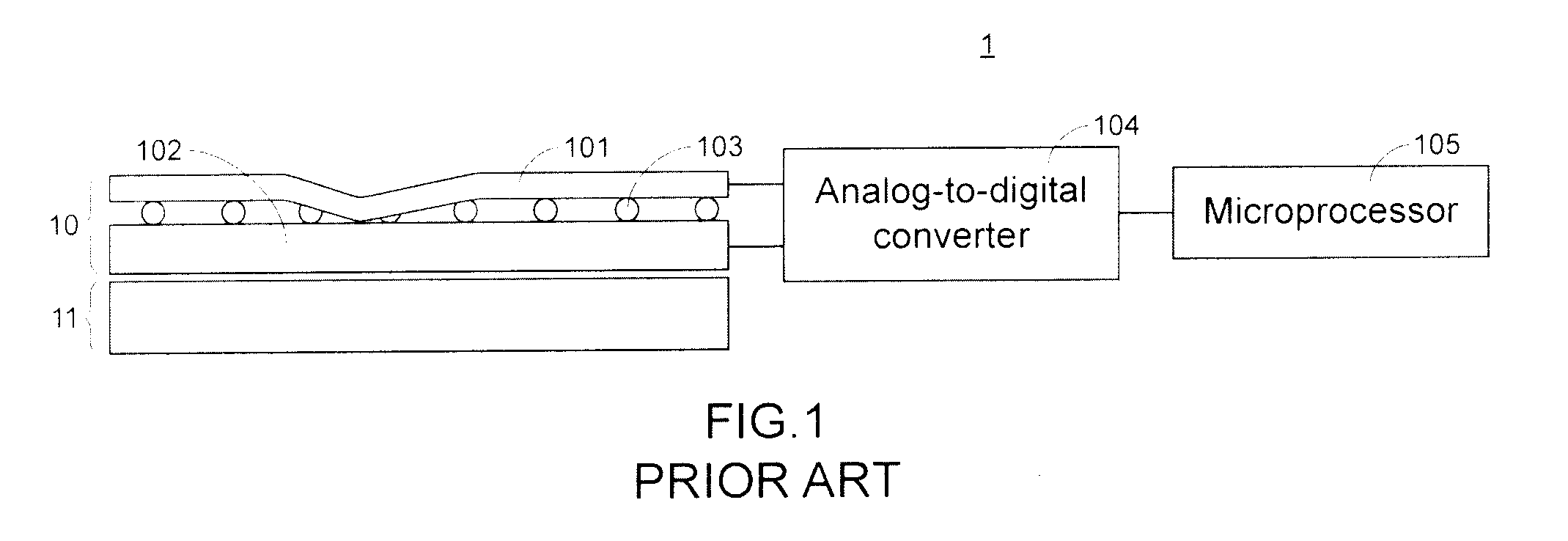
For example, if the transparent conductive film 101 is seriously scratched, the resistive touch panel 10 is possibly subject to a broken circuit and thus the resistive touch panel 10 fails to be normally operated.
Moreover, the resistive touch panel has inferior optical properties and low touch sensitivity.
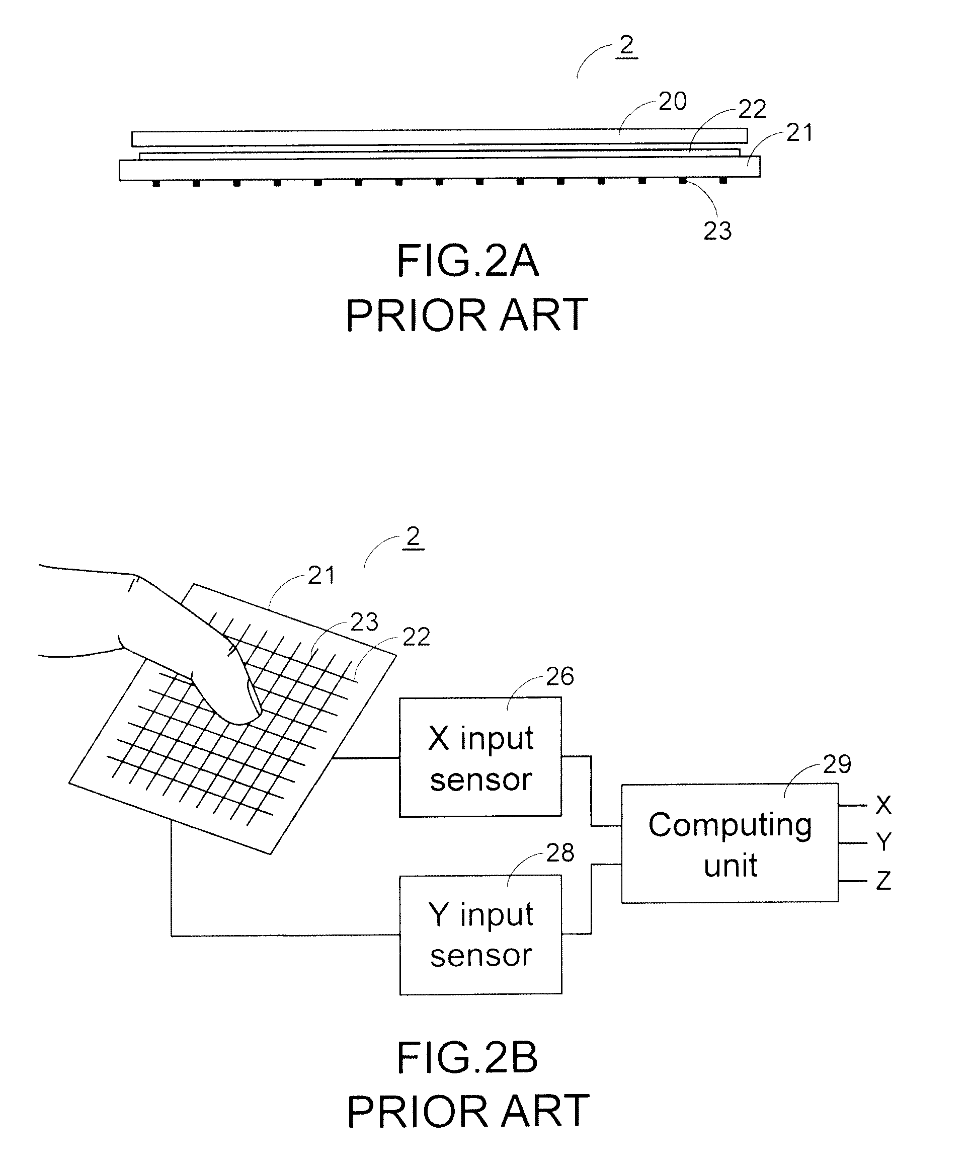
Generally, the conventional capacitive touch panel 2 only responds to finger contact but does not work with a stylus because the contact point of the stylus is much smaller than that of the human finger.
As the number of pins is increased, the space for accommodating the pins is increased, the fabricating cost is increased and the sensing time period is extended.

Method used


Image

  • Device and method for detecting position of object and image display system having such device
  • Device and method for detecting position of object and image display system having such device
  • Device and method for detecting position of object and image display system having such device

Examples


Embodiment Construction

[0024]The present invention will now be described more specifically with reference to the following embodiments. It is to be noted that the following descriptions of preferred embodiments of this invention are presented herein for purpose of illustration and description only. It is not intended to be exhaustive or to be limited to the precise form disclosed.

[0025]FIG. 3 is a schematic top perspective view illustrating a capacitive touch panel according to an embodiment of the present invention. As shown in FIG. 3, a first electrode set and a second electrode set are disposed under a touch film 30. The first electrode set includes multiple first electrodes 31, which are parallel with each other and run in a first direction. The second electrode set includes multiple second electrodes 32, which are parallel with each other and run in a second direction. When an object approaches any one of the first electrodes 31 and the second electrodes 32, the capacitance value is changed. In accor...


PUM


Abstract

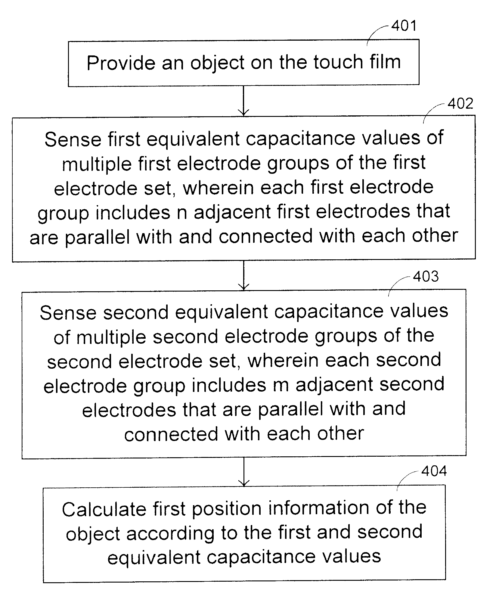
An object position detecting device includes a touch film, a first electrode set, a second electrode set, and a sensing and computing circuit. An object position detecting method includes the following steps. Firstly, an object is provided on the touch film. Then, first equivalent capacitance values of multiple first electrode groups of a first electrode set under the touch film are sensed, wherein each first electrode group includes n adjacent first electrodes that are parallel with and connected with each other. Then, second equivalent capacitance values of multiple second electrode groups of a second electrode set under the touch film are sensed, wherein each second electrode group includes m adjacent second electrodes that are parallel with and connected with each other. According to the first equivalent capacitance values and the second equivalent capacitance values, first position information of the object is calculated.

Description

FIELD OF THE INVENTION[0001]The present invention relates to an object position detecting device and an object position detecting method. The present invention also relates to an image display system having such an object position detecting device.BACKGROUND OF THE INVENTION[0002]As the volume of portable electronic device is gradually reduced, a touch panel display module having an input function and a display function is widely used in the small-sized portable electronic device such as a mobile phone, a personal digital assistant (PDA), a smart phone and the like. FIG. 1 is a schematic cross-sectional view illustrating a touch panel display module according to the prior art. As shown in FIG. 1, the touch panel display module 1 principally comprises a transparent touch panel 10 and a flat display 11. The touch panel 10 is a resistive touch panel. The touch panel 10 comprises a layer of transparent conductive film 101 and a layer of transparent conductive substrate 102. There is a c...

Claims


Application Information

Patent Timeline
Patent Type & Authority Applications(United States)
IPC IPC(8): G06F3/045
CPCG06F3/044G06F3/0416G06F3/047G06F3/04166G06F3/0446
Inventor YANG, KAI-CHIEH
Owner INNOLUX CORP
Learn More