Unlock instant, AI-driven research and patent intelligence for your innovation.

Display control device and display control method

a control device and display control technology, applied in the field of display control devices and display control methods, can solve the problem of difficult to specify the middle position between the screens

Inactive Publication Date: 2010-03-25
KK TOSHIBA
View PDF1 Cites 0 Cited by
  • Summary
  • Abstract
  • Description
  • Claims
  • Application Information

AI Technical Summary

Benefits of technology

[0007]In the above-described prior art, when the proportions of screen sizes of the two screens are changed, the middle position between the screens becomes hard to specify. In consideration of the above situation, an object of the present invention is to provide a display control device and a display control method capable of specifying the boundaries to divide the display region.
[0008]A display control device according to one aspect of the present invention includes a storage module which stores numbers of divisions to divide a display region of a display module in the vertical and horizontal directions; a graduation generation module which generates an image of graduations sh

Problems solved by technology

In the above-described prior art, when the proportions of screen sizes of the two screens are changed, the middle position between the screens becomes hard to specify.

Method used


Image

  • Display control device and display control method
  • Display control device and display control method
  • Display control device and display control method

Examples


first embodiment

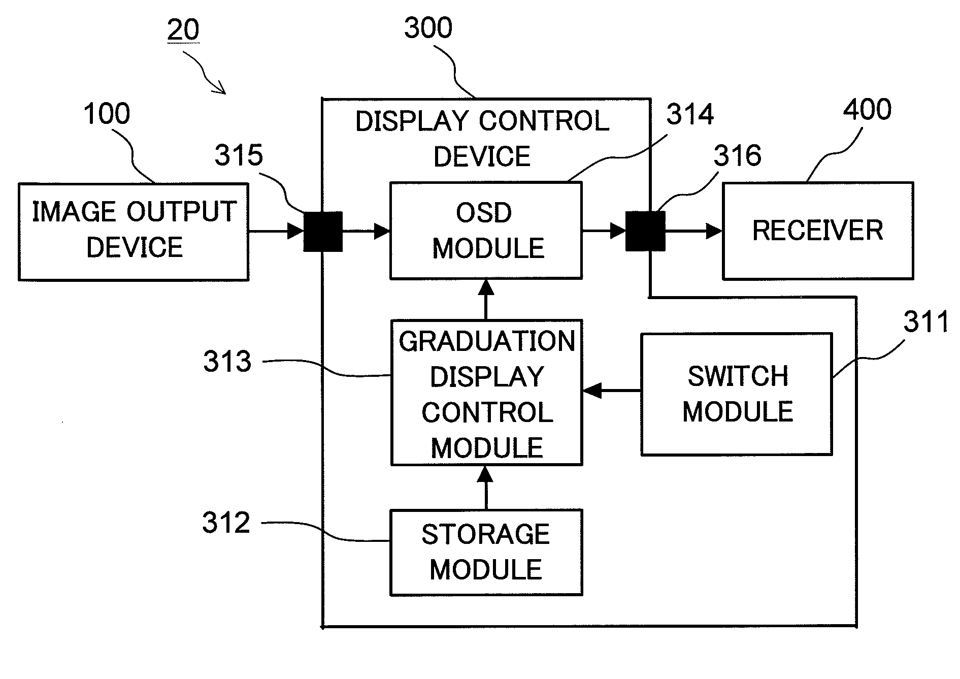
[0018]FIG. 1 is a block diagram showing a display control system 10 according to a first embodiment of the present invention. The display control system 10 comprises an image output device 100 composed of a video game device and so on, and a receiver 200.

[0019]The image output device 100 outputs an image based on detection signals obtained from a later-described plurality of sensor modules 101 to 104. The image output device 100 is electrically connected to the receiver 200 via an input terminal 230. The sensor modules 101 to 104 are arranged at middle positions of a display region 221 of a display module 220 (see FIG. 2). The sensor modules 101 to 104 detect radio signals transmitted from a radio attached, for example, to a human body.

[0020]The receiver 200 comprises a display control device 210 and the display module 220. This receiver 200 displays a screen of an image inputted from the image output device 100.

[0021]The display control device 210 comprises a switch module 211, a s...

modification example 1

[0036]FIG. 5 is a view showing a screen configuration of a display module in a modification example 1 of the first embodiment. Though the images of graduations showing the boundaries for division are arranged around the display region of the display module in the first embodiment, the present invention is not limited to this arrangement.

[0037]In the modification example 1 of the first embodiment, the OSD module 214 displays the images of graduations generated in the graduation display control module 213 in a lattice form over the entire screen in a display region 231 of the display module 220. In this case, it is also possible to display second graduations 232 and 234 in a color different from that of other graduations (first graduations 233 and 235), or display the second graduations 232 and 234 thicker than the other graduations.

[0038]As described above, in the screen configuration of the display module in the modification example 1, the images of graduations are displayed in a la...

modification example 2

[0039]FIG. 6 is a view showing a screen configuration of a display module in a modification example 2 of the first embodiment. FIG. 6 shows a screen configuration in the case where the display module 220 of the receiver 200 has a plurality of display regions. The modification example 2 is an example of a two-screen configuration in which the size of the display region can be changed, composed of, for example, a main screen in a display region 241 and a sub-screen in a display region 251, in which example the middle positions of the main screen are changed with a change in size.

[0040]In this modification example 2, when a switching signal for the main screen is inputted, the graduation display control module 213 generates an image of graduations showing boundaries to divide the display region 241 based on the numbers of divisions and the width of the screen in the display region 241. The OSD module 214 then displays the generated images of graduations around the display region 241 of...


PUM


Abstract

A display control device includes a storage module which stores numbers of divisions to divide a display region of a display module in the vertical and horizontal directions; a graduation generation module which generates an image of graduations showing boundaries to divide the display region of the display module into the numbers of divisions in the vertical and horizontal directions; and a control module which displays the image of graduations generated in the graduation generation module, in the display region.

Description

CROSS-REFERENCE TO RELATED APPLICATIONS[0001]This application is based upon and claims the benefit of priority from the prior Japanese Patent Application No. 2008-241268, filed on Sep. 19, 2008; the entire contents of which are incorporated herein by reference.BACKGROUND OF THE INVENTION[0002]1. Field of the Invention[0003]The present invention relates to a display control device and a display control method of displaying, on a screen, graduations as indexes to arrange an external device near a display module.[0004]2. Description of the Related Art[0005]An external device which outputs an image to a receiver is composed of, for example, a video game device or the like, and is operated in outputting an image by a wireless remote controller or the like. Therefore, a sensor which detects a radio signal may be placed at a predetermined position of the receiver. The sensor is often placed at middle positions in the vertical and horizontal directions of a screen of the receiver on which d...

Claims


Application Information

Patent Timeline
IPC IPC(8): G09G5/00G09G5/377H04N5/44H04N5/66
CPCG09G5/003G09G2340/12G09G5/006
Inventor MATSUO, HIDETOMO
Owner KK TOSHIBA
Features
  • R&D
  • Intellectual Property
  • Life Sciences
  • Materials
  • Tech Scout
  • Unparalleled Data Quality
  • Higher Quality Content
  • 60% Fewer Hallucinations
Learn More