
Detachable structure for ink cartridge

a technology of ink cartridges and connecting sections, which is applied in printing and other directions, can solve the problems of inability to reduce or prevent ink dripping, and ink that dripping may taint user's hands and clothes, and achieve the effect of preventing the leakage of ink from a connecting section of the ink cartridg

Active Publication Date: 2010-03-25
RISO KAGAKU CORP
View PDF5 Cites 17 Cited by
  • Summary
  • Abstract
  • Description
  • Claims
  • Application Information

AI Technical Summary

Benefits of technology

[0009]The above-mentioned structure disclosed in the Patent Document 1 does not taint an attachment section of the ink cartridge in the printer. However, the above-mentioned structure only brings a function for holding the dripping ink and cannot reduce or prevent ink dripping. Therefore, the ink that dripped may taint user's hands and clothes when the ink cartridge is attached or detached. In a case where the ink cartridge is attached or detached in a horizontal direction, dripping amount of ink may increase. It is desired to develop a structure of an ink cartridge that can prevent ink leakage that flowed out from an opening into which an ink supply unit of a printer is inserted or from which the ink supply unit is pulled out when the ink cartridge is attached or detached.
[0010]The present invention has been achieved in order to solve the above problems and an object of the present invention is to provide a detachable structure for an ink cartridge that can prevent ink leakage from a connecting section of the ink cartridge when the ink cartridge is attached-to or detached-from a printer such as an inkjet type printer.
[0012]According to the aspect of the present invention, the anti-outflow member that contacted with the supply port slides outward when the ink cartridge is being detached from the printer. Therefore, ink leakage from the joint section can be prevented by the anti-outflow member and ink can be held within the joint section. Since the insertion rod functions to open the ink supply port by pushing the inner stopper and to guide the anti-outflow member sliding, ink can be firmly guided to flow into the joint section through the ink supply port and ink leakage from the joint section after detaching the ink cartridge can be prevented firmly.
[0014]It is preferable that the anti-outflow member includes a plate having an outer shape corresponding to an inner shape of the ink flow path and an insertion hole having an inner diameter larger than the an outer diameter of the insertion rod to make an ink flow path between the plate and the insertion rod. In this case, it can be done by ink flowing through the insertion hole to supply ink from the ink cartridge to the printer. Since the insertion hole is made larger than the outer diameter of the insertion rod and the insertion hole is located at the center of the plate, ink flow can be ensured on supplying ink and ink can be supplied flawlessly. In addition, ink within the joint section can be held due to surface tension of the ink after the ink cartridge is detached from the printer.
[0015]Alternatively, it is preferable that the anti-outflow member includes a plate having an outer shape corresponding to an inner shape of the ink flow path, a plurality of through holes provided on an outer circumference of the plate formed on the plate and a plurality of bumps provided on one surface of the plate that faces the ink supply port. In this case, it can be done by ink flowing through the through holes to supply ink from the ink cartridge to the printer. Since a gap can be made as an ink flow path between the inner stopper (the ink supply port) and the plate due to presence of the bumps, ink flow through the ink flow path can be ensured on supplying ink and ink can be supplied flawlessly. Further, ink within the joint section can be held due to surface tension of the ink after the ink cartridge is detached from the printer.
[0017]As described above, according to the structure of the present invention, ink leakage from a connecting section of the ink cartridge can be prevented when the ink cartridge is attached-to or detached-from a printer such as an inkjet type printer.

Problems solved by technology

However, the above-mentioned structure only brings a function for holding the dripping ink and cannot reduce or prevent ink dripping.
Therefore, the ink that dripped may taint user's hands and clothes when the ink cartridge is attached or detached.

Method used


Image

  • Detachable structure for ink cartridge
  • Detachable structure for ink cartridge
  • Detachable structure for ink cartridge

Examples


Embodiment Construction

General Configuration of Printer

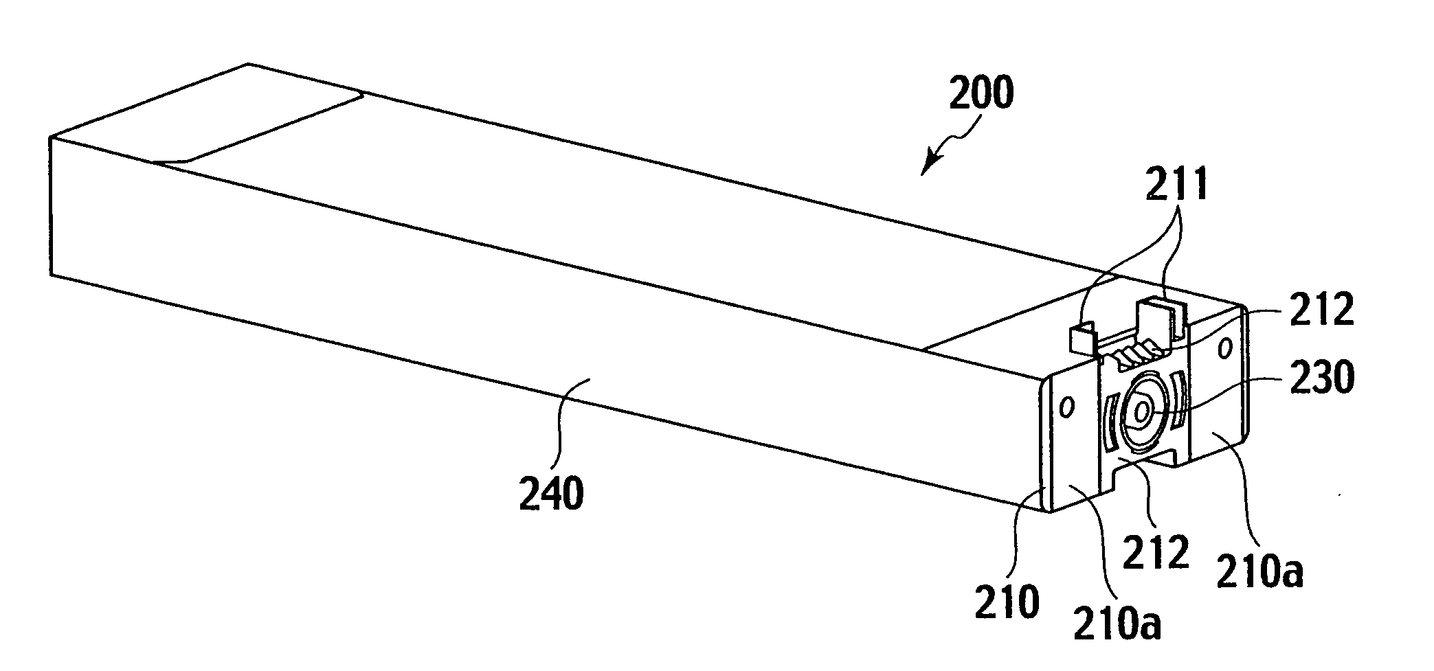
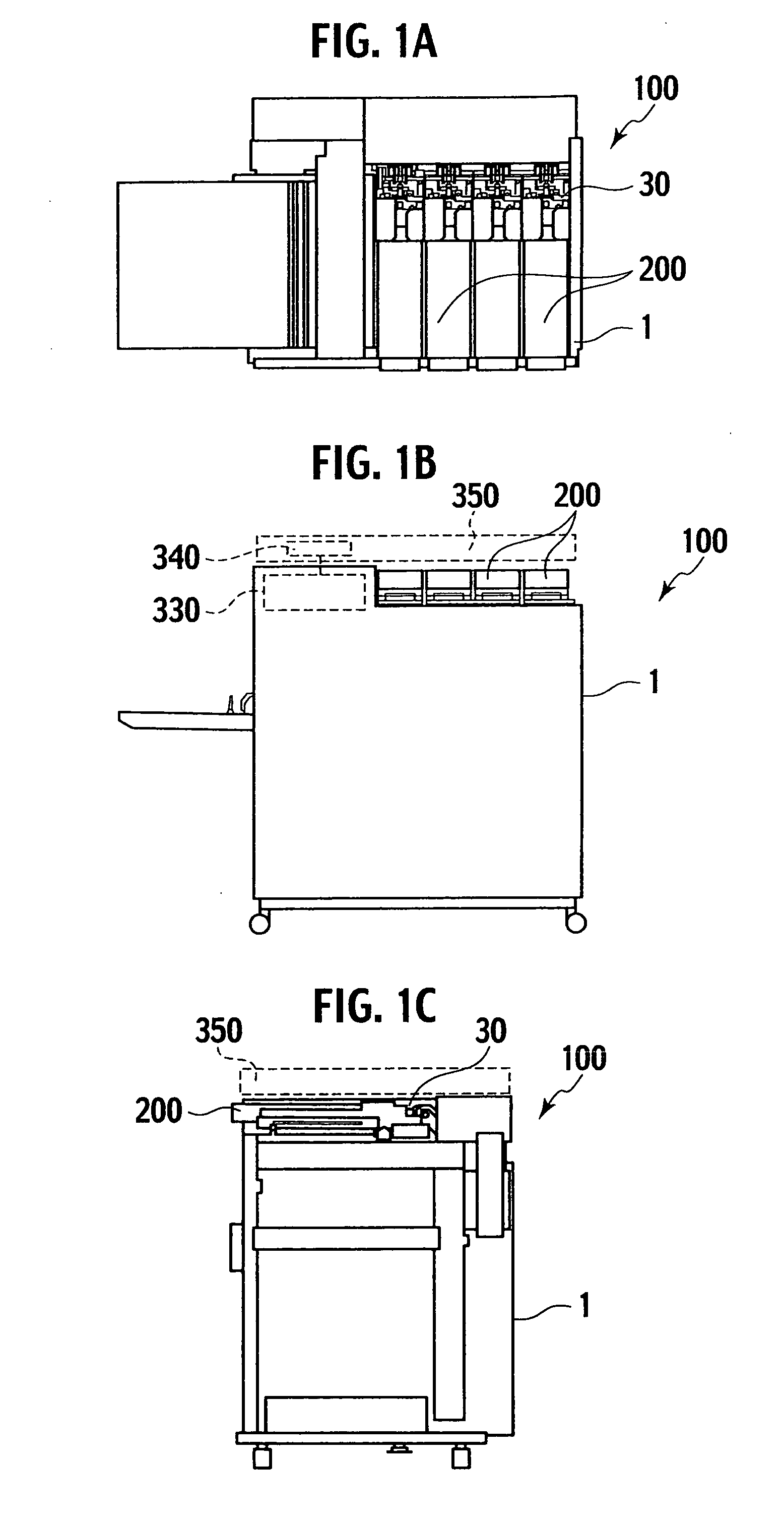
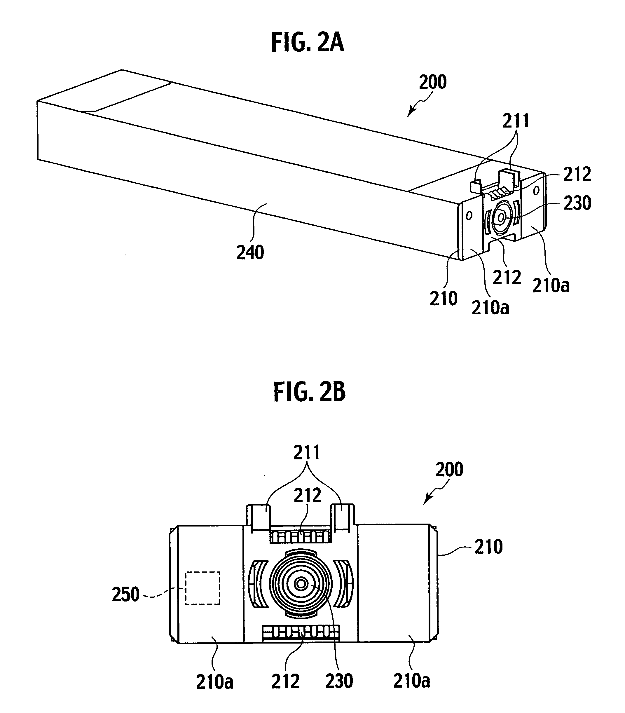
[0038]One embodiment of a detachable structure for an ink cartridge according to the present invention will be explained with reference to the drawings. A printer 100 having the detachable structure is an inkjet type color line printer. The printer 100 includes a plurality of ink heads each has a number of nozzles. Printing is done line by line by ejecting black and / or color ink drops from the nozzles onto a printing paper (sheet) on a feeding belt so as to overlap images each other.

[0039]Four of the four ink heads are aligned and provided for yellow (Y), magenta (M), cyan (C) and black (K) inks for forming color images so as to overlap images formed by the respective ink heads. A processing unit 330 is provided within the printer 100. The processing unit 330 controls the above-mentioned printing processes by the ink heads, a drive control of a feed mechanism, a supply control of inks supplied from ink cartridges 200 and so on.

[0040]The processing uni...


PUM


Abstract

A detachable structure for an ink cartridge includes a supply port, a joint section, an insertion rod and an anti-outflow member. The port is provided in the cartridge. The stopper is provided in the port and urged outward to close the port. The joint section is provided in a printer and coupled with the port. The joint section has an ink flow path that communicates with the port while the port is coupled. The insertion rod is provided in the joint section for pushing the stopper inward to communicate the ink flow path with the port while the port is coupled. The anti-outflow member is slidably provided in the joint section. The anti-outflow member is urged outward and slides along the insertion rod when the port is being inserted into the joint section. According to the structure, ink leakage on attaching or detaching of the cartridge can be prevented.

Description

BACKGROUND OF THE INVENTION[0001]1. Field of the Invention[0002]The present invention relates to a detachable structure for an ink cartridge in a printer.[0003]2. Description of Related Art[0004]With respect to an inkjet printer, printing speed becomes higher and an image size to be printed becomes larger in recent days and thereby ink consumption increases. Therefore, larger ink supply amount from an ink cartridge to an inkjet printer is required. In a conventional ink supply method for an inkjet printer, an ink supply needle is inserted into an ink container in an ink cartridge in order to extract ink. However, ink flow amount is small in the conventional method and thereby the conventional method cannot meet the requirement of larger ink supply amount due to higher printing speed and larger image size. Therefore, a joint mechanism with an inner stopper and an O-ring is used to make supply amount larger in recent days.[0005]Compared with ink supplying through the ink supply needle...

Claims


Application Information

Patent Timeline
Patent Type & Authority Applications(United States)
IPC IPC(8): B41J2/175
CPCB41J2/17509B41J2/17513B41J2/17566B41J2/17553B41J2/17523
Inventor AKIYAMA, TOMOYUKI
Owner RISO KAGAKU CORP
Learn More