Passive Ventilation For Outdoor Electrical Enclosures

an electrical enclosure and passive ventilation technology, applied in the field of outdoor enclosures, can solve the problems of shortening the life expectancy of costly electrical components, sensitive electronics, and damaging the contents inside the enclosure, and achieve the effects of preventing overheating, simple and robust, and reliable solution

Active Publication Date: 2010-03-25
SIEMENS IND INC
View PDF22 Cites 7 Cited by
  • Summary
  • Abstract
  • Description
  • Claims
  • Application Information

AI Technical Summary

Benefits of technology

[0012]Another purpose of this invention is to keep the inside of an outdoor electrical enclosure ventilated to prevent overheating.
[0013]Still, another purpose of this invention is to provide a reliable solution for venting of outdoor electrical enclosures.
[0014]Yet, another purpose of this invention is to provide a simple and a robust solution for venting of outdoor electrical enclosures.

Problems solved by technology

The accumulation of heat in an enclosure can be damaging to the contents inside the enclosure, especially, sensitive electronics.
For example, overheating can shorten the life expectancy of costly electrical components or lead to catastrophic failure.

Method used


Image

  • Passive Ventilation For Outdoor Electrical Enclosures
  • Passive Ventilation For Outdoor Electrical Enclosures
  • Passive Ventilation For Outdoor Electrical Enclosures

Examples


first embodiment

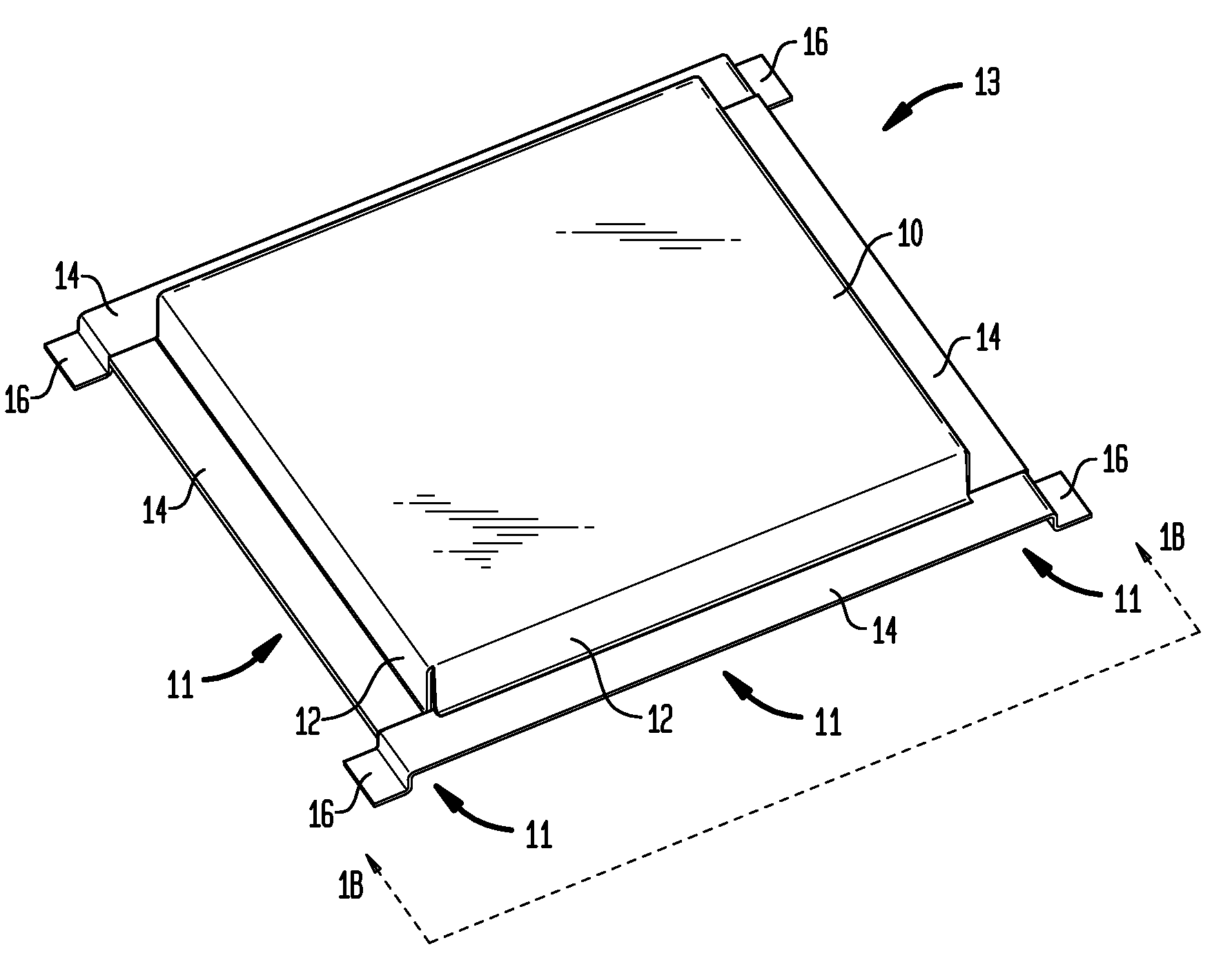
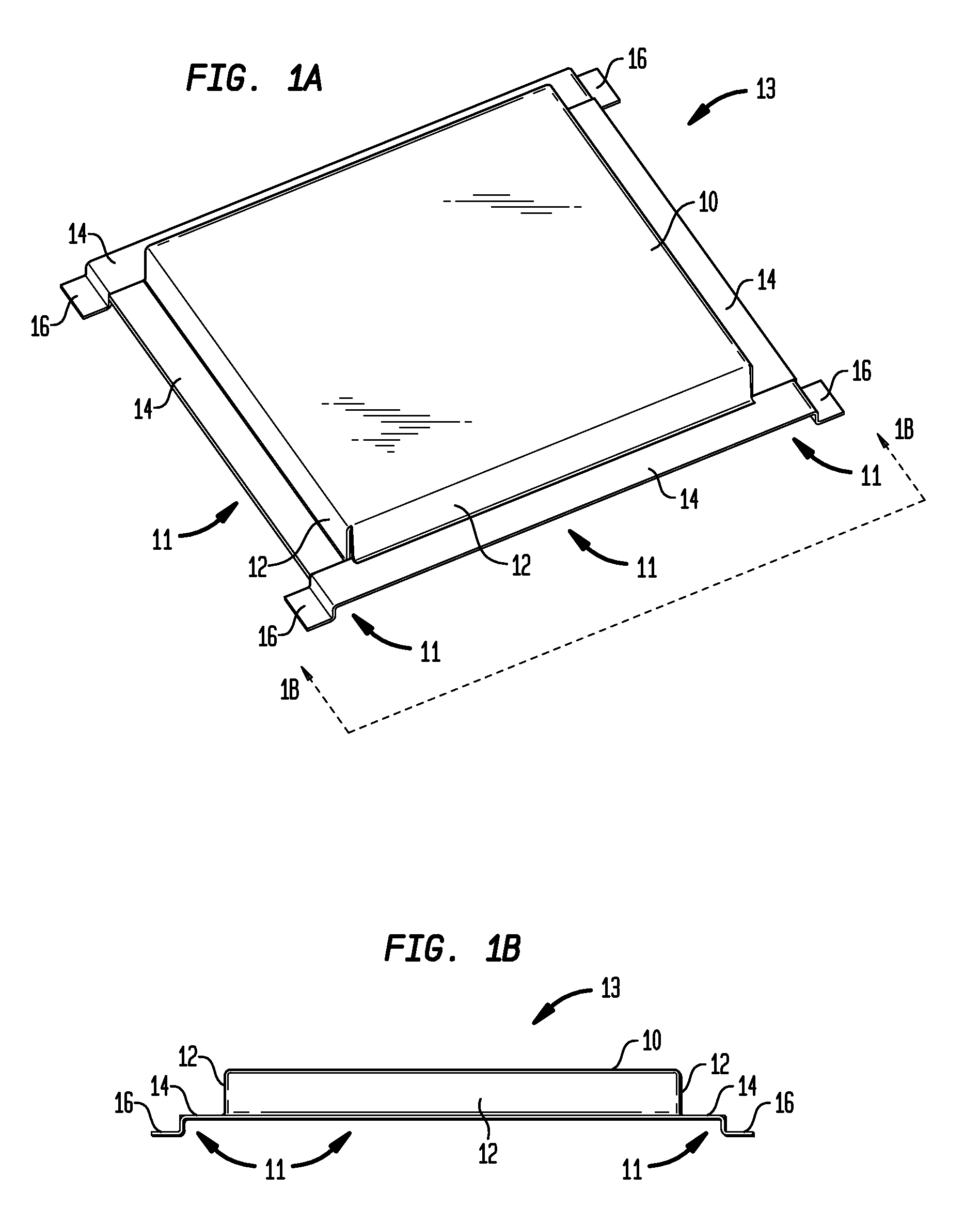
[0029]FIG. 1A illustrates a perspective view of the inventive passive ventilation apparatus 13, of this invention. The inventive passive ventilation apparatus 13, comprises a top or main cover 10. The main cover 10, has at least one vertical wall or flange 12, around at least a portion of the peripheral edge of the main cover 10. It is preferred that the vertical wall or flange 12, is substantially vertical to the plane of the main cover 10, however, for some applications the vertical wall or flange 12, could have an angle of between about 30 degrees to about 150 degrees to the plane of the main cover 10, and preferably have an angle of between about 60 degrees to about 120 degrees to the plane of the main cover 10, and more preferably have an angle of between about 80 degrees to about 100 degrees to the plane of the main cover 10. Secured to at least a portion of the vertical wall or flange 12, is at least one horizontal wall or flange 14, and which is around at least a portion of ...

second embodiment

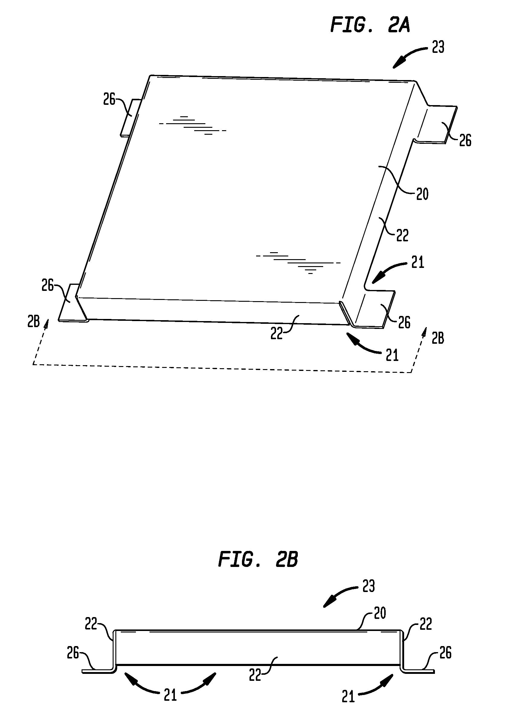
[0031]FIG. 2A illustrates a perspective view of the inventive passive ventilation apparatus 23, of this invention. The inventive passive ventilation apparatus 23, comprises a top or main cover 20. The main cover 20, has at least one vertical wall or flange 22, around at least a portion of the peripheral edge of the main cover 20. It is preferred that the vertical wall or flange 22, is substantially vertical to the plane of the main cover 20, however, for some applications the vertical wall or flange 22, could have an angle of between about 30 degrees to about 150 degrees to the plane of the main cover 20, and preferably have an angle of between about 60 degrees to about 120 degrees to the plane of the main cover 10, and more preferably have an angle of between about 80 degrees to about 100 degrees to the plane of the main cover 20. Secured to at least a portion of the peripheral edge of the vertical flange 22, is at least one feet or flap or step or tab or spacer 26. Care should be ...

third embodiment

[0033]FIG. 3A illustrates a perspective view of the inventive passive ventilation apparatus 33, of this invention. The inventive passive ventilation apparatus 33, comprises a top or main cover 30. The main cover 30, has at least one vertical wall or flange 32, around at least a portion of the peripheral edge of the main cover 30. It is preferred that the vertical wall or flange 32, is substantially vertical to the plane of the main cover 30, however, for some applications the vertical wall or flange 32, could have an angle of between about 30 degrees to about 150 degrees to the plane of the main cover 30, and preferably have an angle of between about 60 degrees to about 120 degrees to the plane of the main cover 30, and more preferably have an angle of between about 80 degrees to about 100 degrees to the plane of the main cover 30. Secured to at least a portion of the vertical wall or flange 32, is at least one horizontal wall or flange 34, and which is around at least a portion of ...


PUM


Abstract

The present invention relates generally to outdoor enclosures. More particularly, the invention encompasses passive ventilation for an outdoor electrical enclosure. The present invention is also directed to a novel passive ventilation apparatus that is secured to an outdoor electrical enclosure. The novel passive ventilation apparatus has at least one vent or opening or gap to allow for the ventilation of air, moisture, humidity, and other fluids from an outdoor electrical enclosure. The outdoor electrical enclosure also has at least one venting means to vent air, moisture, humidity, or other fluids from inside the outdoor electrical enclosure. The outdoor electrical enclosure also has at least one means to prevent any debris from falling inside the outdoor electrical enclosure.

Description

CROSS-REFERENCE TO RELATED APPLICATION[0001]The instant patent application claims priority to and the benefit of pending U.S. Provisional Patent Application Ser. No. 61 / 099,280, filed on Sep. 23, 2008, titled “Passive Ventilation For Outdoor Electrical Enclosures,” the entire disclosure of which provisional application is incorporated herein by reference.FIELD OF THE INVENTION[0002]The present invention relates generally to outdoor enclosures; More particularly, the invention encompasses passive ventilation for an outdoor electrical enclosure. The present invention is also directed to a novel passive ventilation apparatus that is secured to an outdoor electrical enclosure. The novel passive ventilation apparatus has at least one vent or opening or gap to allow for the ventilation of air, moisture, humidity, and other fluids from an outdoor electrical enclosure. The outdoor electrical enclosure also has at least one venting means to vent air, moisture, humidity, or other fluids from ...

Claims


Application Information

Patent Timeline
Patent Type & Authority Applications(United States)
IPC IPC(8): F24F13/20
CPCH05K7/20127
Inventor RICO, GUSTAVO CORTES
Owner SIEMENS IND INC
Why Eureka
Try Eureka