Power crimping device and method for crimping building panels

Inactive Publication Date: 2010-04-01
MIC IND INC
View PDF11 Cites 0 Cited by
  • Summary
  • Abstract
  • Description
  • Claims
  • Application Information

AI Technical Summary

Benefits of technology

[0010]The exemplary devices and methods disclosed herein may provide certain advantages. One advantage is to reduce operator fatigue and make the crimping process easier by using rotary motion to constantly move the crimping blades in a repeatable open and close motion as long as power is maintained on the motor. Another advantage is to allow a crimping device to easily fit into a confined space. Because of the rotary motion and co

Problems solved by technology

The present inventors have observed, however, that attempting to crimp building panels within a confined space, such as a concrete foundation form, can be difficult because the distance between the foundation form and the panels may be insuffici

Method used


Image

  • Power crimping device and method for crimping building panels
  • Power crimping device and method for crimping building panels
  • Power crimping device and method for crimping building panels

Examples


Example

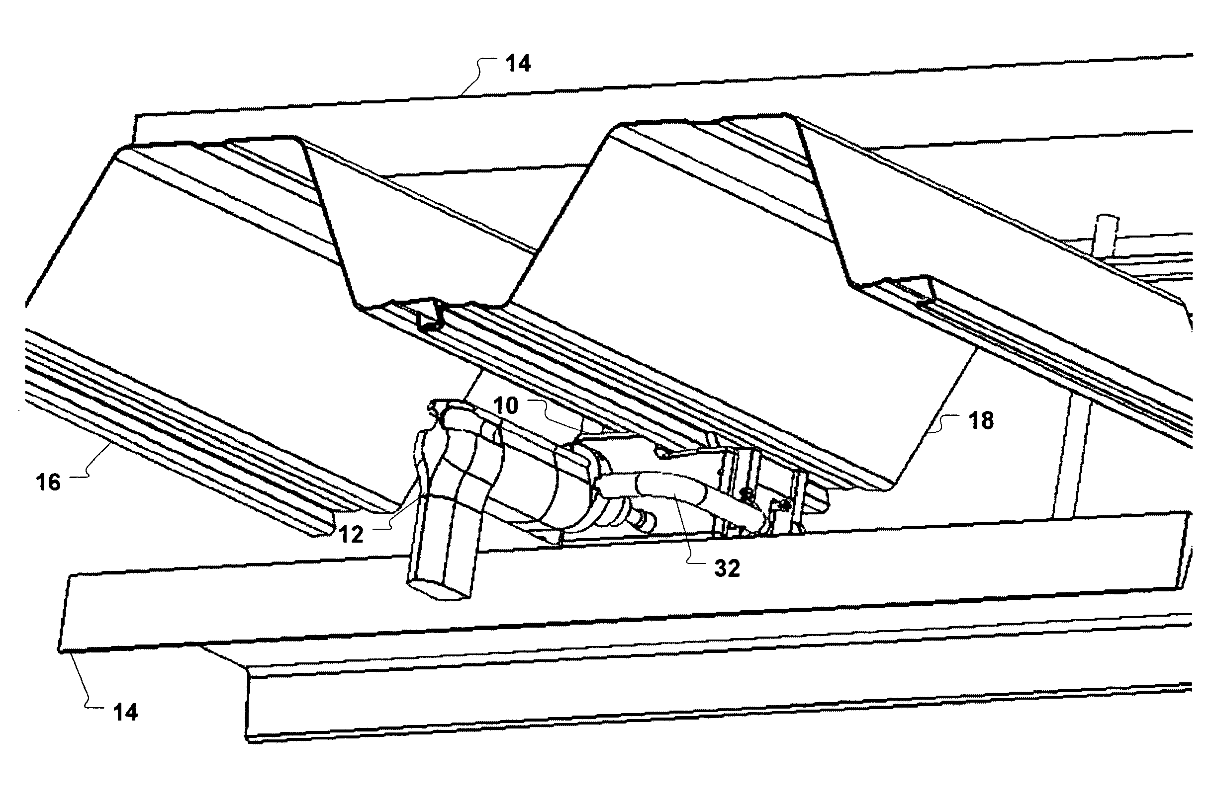
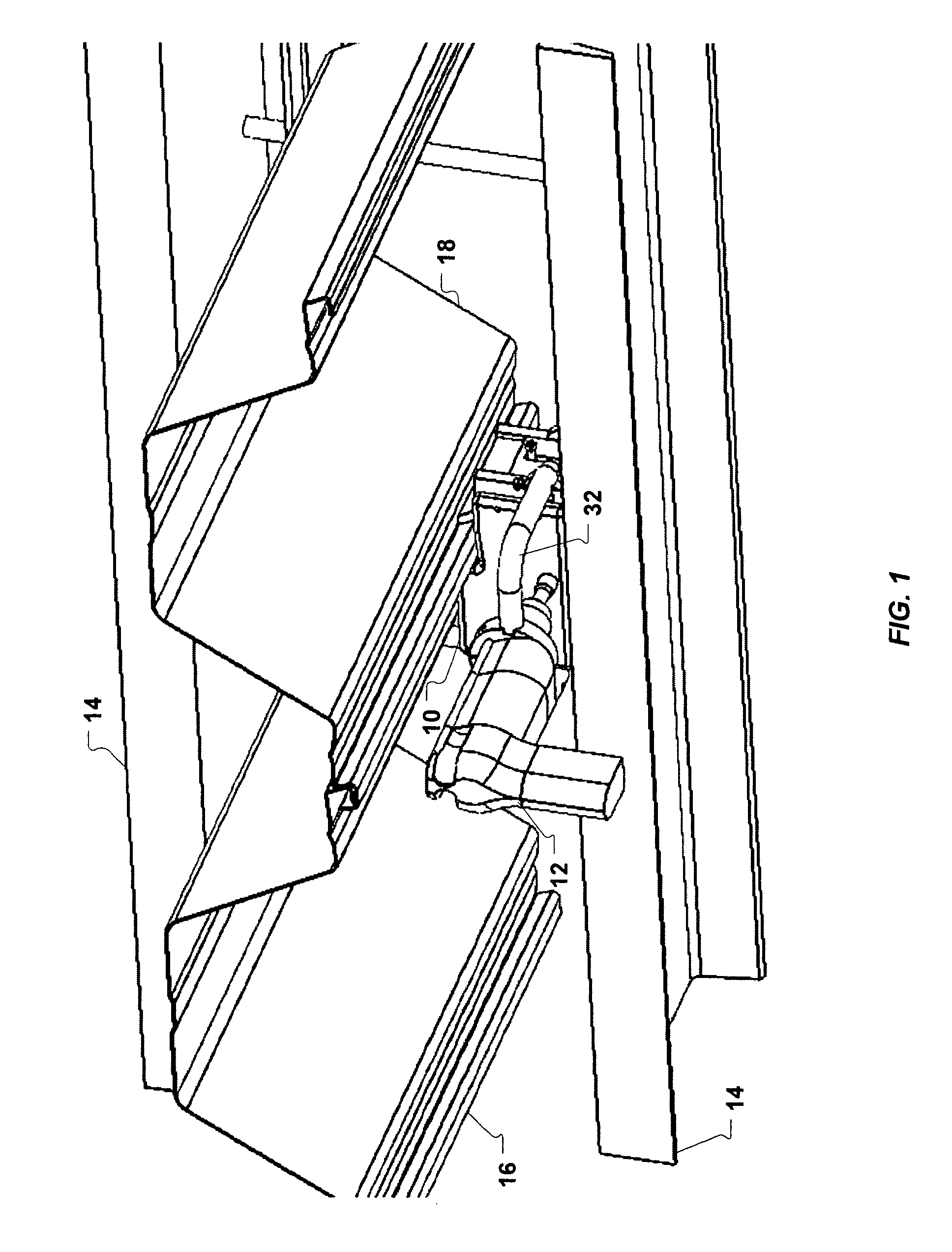
[0025]Certain features of the exemplary embodiments described herein are described with reference to directions, e.g., up, and down. With reference to FIG. 1, for the purposes of this disclosure, up, upwardly, and the like refers to a direction from the crimping device 10 generally toward the building panels 16, 18. Down, downwardly, and the like refers to the direction from the building panels 16, 18 generally toward the crimping device 10. Thus the top of the crimping device 10 would refer to a side of the crimping device facing the building panels 16, 18 and the bottom of the crimping device 10 would refer to an opposing side of the crimping device 10, for example. Obviously the directions are relative and are described for illustrative purposes only—they should not be construed to limit the scope of the disclosure or the claims.

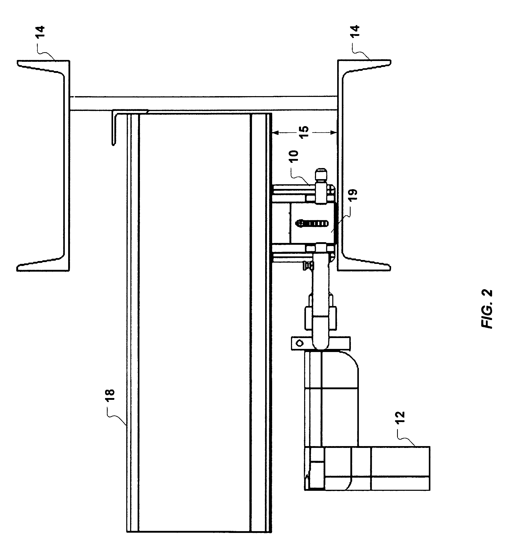
[0026]FIGS. 1-7 illustrate an exemplary crimping device 10 for crimping together edge portions of adjacent building panels in accordance with certain emb...


PUM

PropertyMeasurementUnit
Heightaaaaaaaaaa
Heightaaaaaaaaaa

Abstract

An device for crimping together adjacent edge portions of two building panels including a frame supporting a rotatable shaft protruding therethrough, a first crimping member attached to the frame, a gear train supported by the frame coupled to the rotatable shaft such that a rotation of the rotatable shaft imparts rotary motion to the gear train, a drive mechanism supported by the frame and rotatably coupled to the gear train, and a second crimping member supported by the frame and coupled to the drive mechanism, wherein the second crimping member is configured to move toward and then away from the first crimping member in a repeating, reciprocating motion under influence of the drive mechanism while rotation of the rotatable shaft is maintained, such that the second crimping member is configured to bend an edge portion of a first building panel over an edge portion of a second building panel.

Description

BACKGROUND[0001]1. Field of the Disclosure[0002]The present disclosure relates to a crimping device and method for crimping together edge portions of adjacent building panels.[0003]2. Background Information[0004]Construction techniques are known for constructing buildings using adjacent metal building panels that are attached together at their adjacent edges. Such building panels may include a main portion from which side edge portions extend. The side edge portions may be configured so that the edge of one panel can be disposed inside the edge of another panel and then crimped together. Once the panels have been crimped together, a rotary seam forming device can be applied to the panels to form a more watertight seam. Devices for crimping the building panels together are known in the art and are commercially available from M. I. C. Industries, Inc. of Reston, Va. Exemplary devices are shown, for example, in U.S. Pat. No. 5,243,748, which is owned by M. I. C. Industries, Inc.[0005]T...

Claims


Application Information

Patent Timeline
IPC IPC(8): B25B7/12B23P11/00
CPCE04D3/364Y10T29/53709E04D15/04
Inventor POPOVITCH, LOU S.
Owner MIC IND INC
Why Eureka
Try Eureka