Dismantleable apparatus for transferring fluids between containers

a technology of fluid transfer and container, which is applied in the direction of liquid handling, transportation and packaging, and packaging of goods, etc., can solve the problems of large increase in the cost of lubricating oil, whether for an engine or a transmission, and the inlet to such containers is relatively small, so as to achieve the effect of little probability of spillag

Inactive Publication Date: 2010-04-08
BONNELL DONALD G
View PDF22 Cites 6 Cited by
  • Summary
  • Abstract
  • Description
  • Claims
  • Application Information

AI Technical Summary

Benefits of technology

This invention has an attachment that supports a platform which allows for easy removal of different posts. There is also a collection device that can hold lubricant oil without leaking or splashing when draining it from its holder. Additionally, there are removable parts called a tray that can help keep things organized while they are being cleaned. Overall, this invention makes it easier to manage and use oily substances in industrial settings.

Problems solved by technology

The technical problem addressed in this patent text relates to the difficulty and messiness of changing lubricating oil in vehicles due to high costs of the oil and limited availability of convenient storage options. There also exists a safety issue when dealing with hot engines and transmissions after they have been running without proper oil levels. This results in incomplete drainage of the old oil which leads to waste and increases the risk of environmental contamination.

Method used


Image

  • Dismantleable apparatus for transferring fluids between containers
  • Dismantleable apparatus for transferring fluids between containers
  • Dismantleable apparatus for transferring fluids between containers

Examples


Embodiment Construction

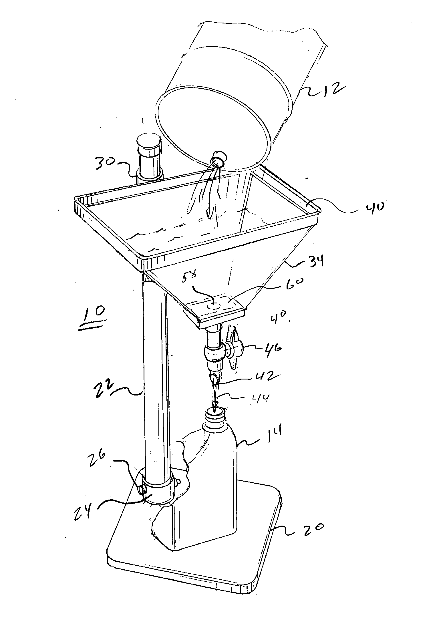
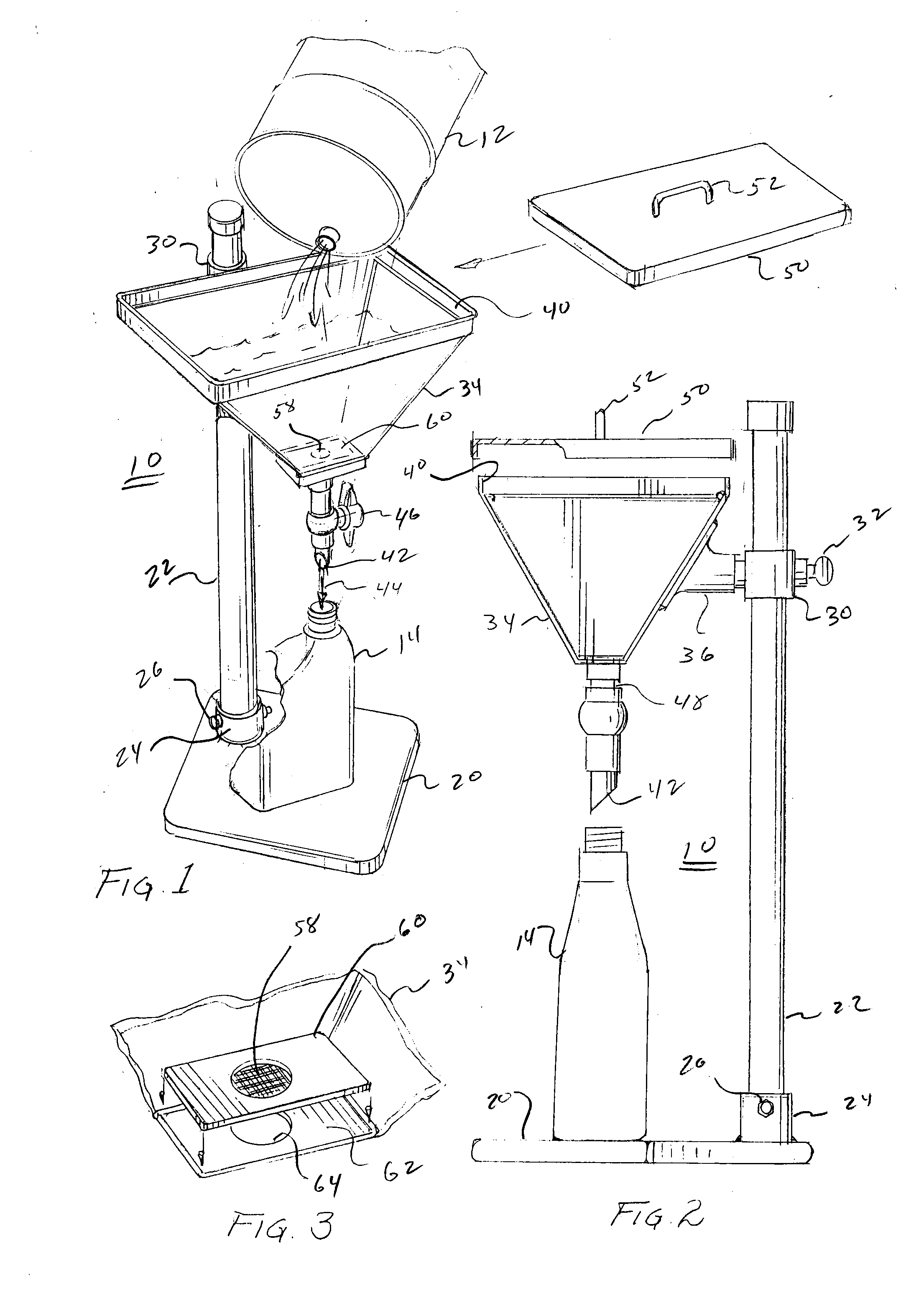
[0033]Referring to FIG. 1, there is illustrated apparatus 10 for collecting a fluid from a container 12 into a flask 14; it is to be understood that the element identified by the term flask could be any type of capped or uncapped container. Apparatus 10 includes a base 20 for supporting a post 22. The post nests within a cylinder 24 extending from base 20. Set screws 26, or the like, extend through cylinder 24 into locking engagement with the post to permit insertion and withdrawal from the post.

[0034]As further shown in FIG. 2, a collar 30 is slidably mounted upon post 22 and includes a set screw 32 for lockingly engaging the collar with the post at a selected height. A collector 34 is engaged with collar 30 through a support 36. Accordingly, the vertical location of collector 34 relative to base 20 is a function of the location at which collar 30 is locked onto post 22. As particularly illustrated in FIG. 1, the collector is generally in the shape of an inverted hollow pyramid hav...


PUM


Abstract

A combination fluid collector and parts washer includes a collector mounted on a base supported stanchion to receive fluid for selectively discharging the fluid through a valve into a container. A tray is removably mounted in the collector for supporting parts to be washed by the fluid in the collector and includes ridges on the bottom for drainage purposes and holes for draining the fluid from the tray into the collector. A device for collecting fluid from each of a plurality of containers is detachably attachable to the stanchion for discharging the collected fluid into a vessel.

Description


Claims


Application Information

Patent Timeline
Owner BONNELL DONALD G
Why Eureka
Try Eureka