Apparatus for using heat pipes in controlling temperature of an LED light unit

a technology of led light units and heat pipes, which is applied in the direction of lighting and heating apparatus, landing aids, lighting applications, etc., can solve the problems of limited power levels of leds and difficult routine maintenance (such as the replacement of flash tubes)

Active Publication Date: 2010-04-08
DIALIGHT CORP
View PDF18 Cites 67 Cited by
  • Summary
  • Abstract
  • Description
  • Claims
  • Application Information

AI Technical Summary

Benefits of technology

[0006]In one embodiment, the present invention provides a light emitting diode (LED) light unit. The LED light unit comprises at least one support plate having one or more inner openings, at least one LED array coupled to an LED board and at least one heat pipe coupled to said LED board, wherein said LED board is coupled to said at least one support plate.

Problems solved by technology

In the past light emitting diodes (LEDs) were limited to power levels under a watt.
Such locations make the performance of routine maintenance (such as replacing the flashtube) extremely difficult.

Method used


Image

  • Apparatus for using heat pipes in controlling temperature of an LED light unit
  • Apparatus for using heat pipes in controlling temperature of an LED light unit
  • Apparatus for using heat pipes in controlling temperature of an LED light unit

Examples


Embodiment Construction

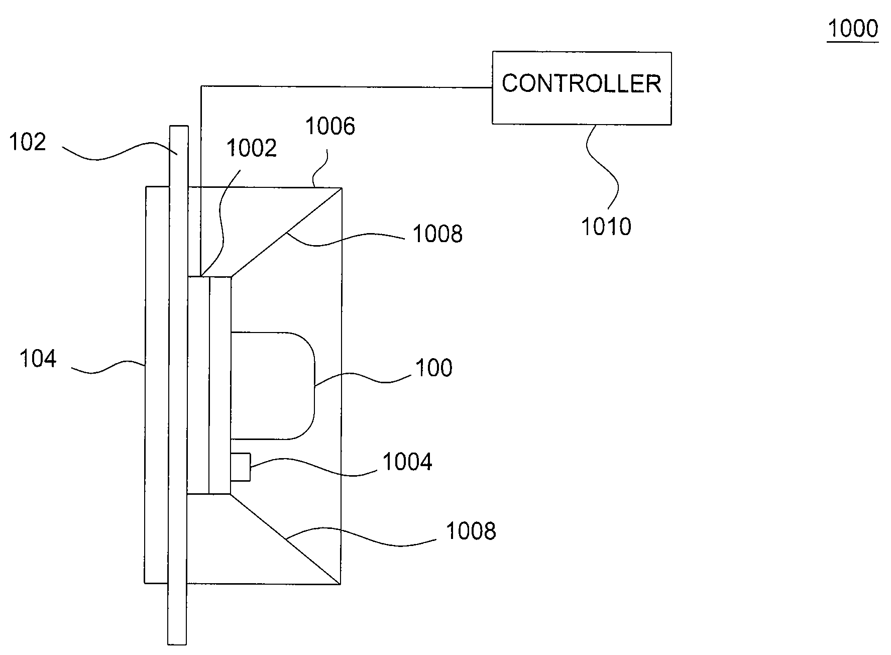
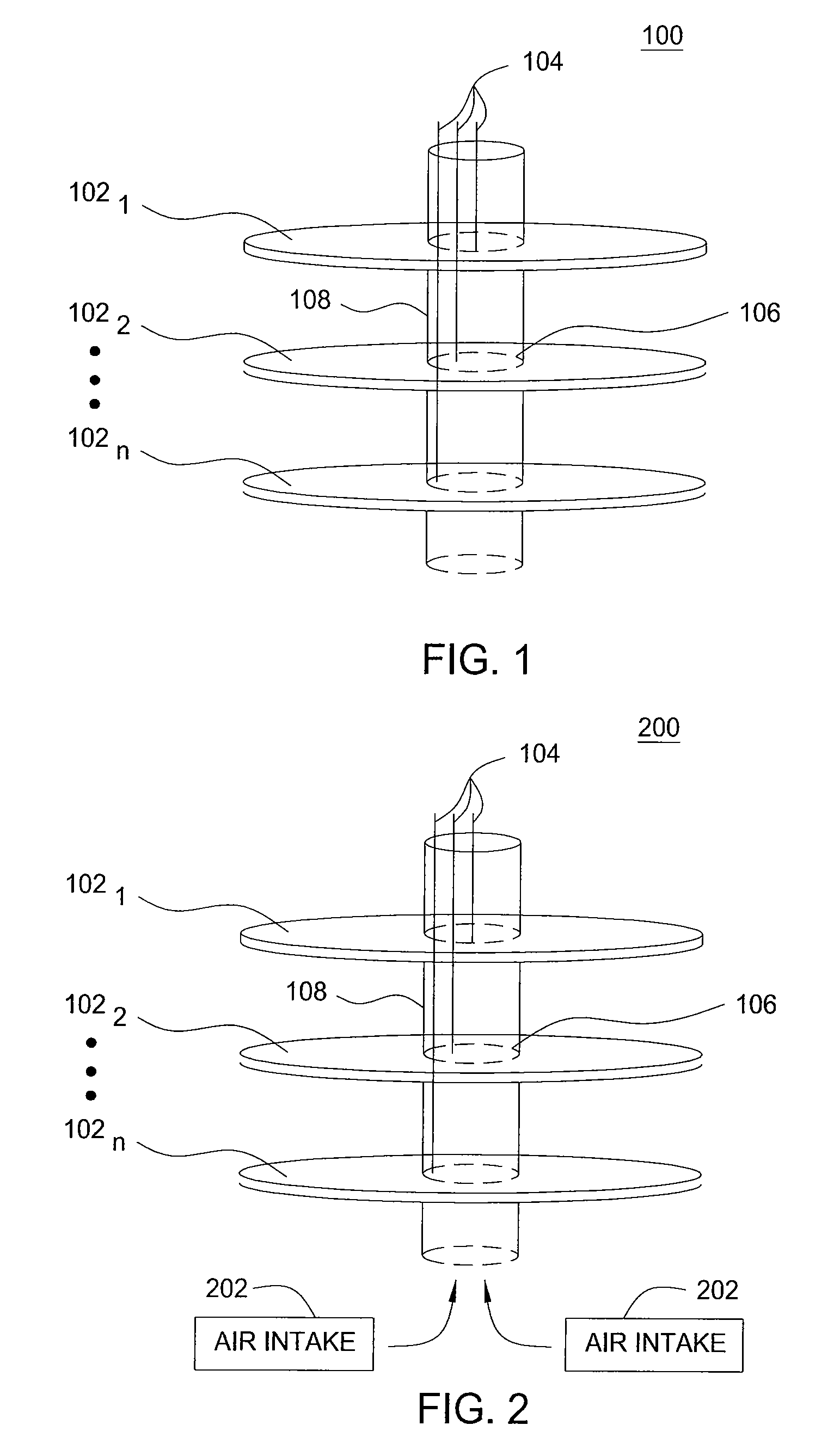
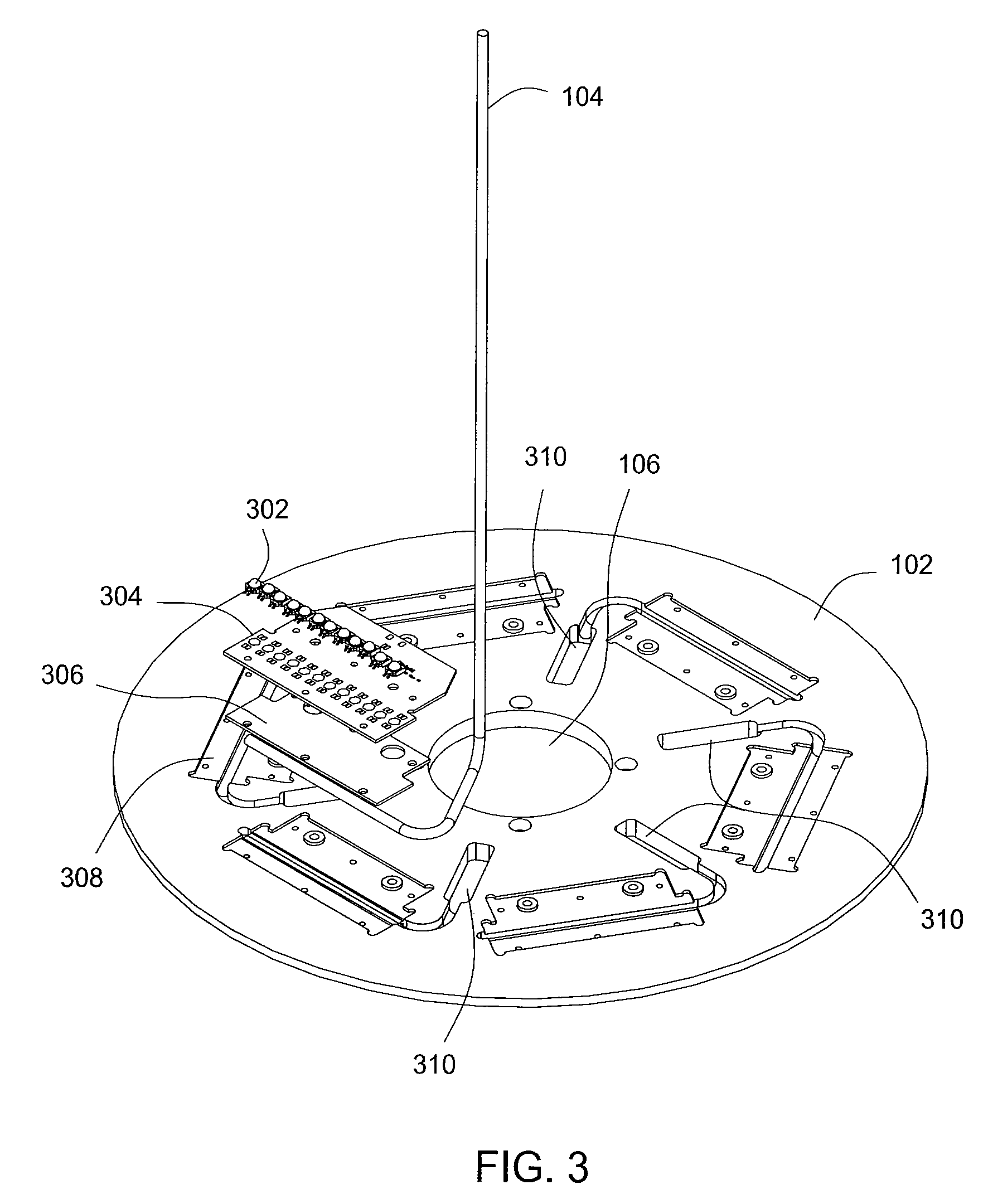
[0022]FIG. 1 illustrates a high level block diagram of an exemplary embodiment of a light emitting diode (LED) light unit 100 of the present invention. The LED light unit 100 may be, for example, a beacon placed on radio transmission towers, wind turbine generators, refinery stacks and the like. The LED light unit 100 may utilize LEDs that flash, for example in a strobe unit, or LEDs that continuously emit light, for example that are always in an on position. The LED light unit 100 may include at least one support plate 1021 to 102n. Hereinafter, the support plates 1021 to 102n may be referred to individually or collectively as support plate 102. The support plate 102 may be any geometry, for example circular or any polygonal shape, for example a square, hexagon, octagon and the like. In an exemplary embodiment, the support plate 102 may be circular for the purposes of discussing the present invention. Furthermore, the support plate 102 may be constructed from any thermally conducti...


PUM


Abstract

A light emitting diode (LED) light unit is disclosed. For example, the LED light unit includes at least one support plate having one or more inner openings. At least one LED array may be coupled to an LED board. The LED light unit also includes at least one heat pipe coupled to the LED board, wherein said LED board is coupled to the at least one support plate.

Description

CROSS REFERENCE TO RELATED APPLICATIONS[0001]This application is a continuation-in-part of recently allowed U.S. patent application Ser. No. 11 / 770,538, filed on Jun. 28, 2007, which claims priority under 35 U.S.C. §119(e) to This application claims the benefit of U.S. Provisional Patent Application No. 60 / 817,880 filed on Jun. 30, 2006, which is herein incorporated by reference.FIELD OF THE INVENTION[0002]The present invention relates generally to removing heat from an LED light unit and more specifically to heat pipes and thermoelectric coolers for controlling temperature of an LED light unit.BACKGROUND OF THE INVENTION[0003]In the past light emitting diodes (LEDs) were limited to power levels under a watt. LEDs are now available in packages over five watts. LEDs are now also available with efficiencies of 100 lumens / watt. These recent advancements have enabled many new applications for LEDs. One example is the use of LEDs for warning devices such as beacon lights. Beacon lights t...

Claims


Application Information

Patent Timeline
Patent Type & Authority Applications(United States)
IPC IPC(8): B60Q1/02F21S4/00B60Q1/00H01J13/32H05B44/00
CPCF21K9/00F21V29/89F21V23/0442F21V29/006F21W2111/00F21Y2101/02F21Y2103/003B64F1/20B64D2203/00F21W2111/06F21V29/20H05B33/089F21V29/54F21V29/713F21V29/75F21V29/763F21S48/328F21Y2103/10F21Y2115/10F21S45/49F21S45/42F21S45/30F21S45/60F28D15/0275F21V29/51F21S45/48H05B45/56
Inventor BURTON, THOMAS R.CURRAN, JOHN W.PECK, JOHN PATRICKZIMMER, KENNETH J.BALCZAREK, GREGORY K.
Owner DIALIGHT CORP
Why Eureka
Try Eureka