
Driving cricuit and gray insertion method of liquid crystal display

a liquid crystal display and gray insertion technology, applied in the direction of instruments, computing, electric digital data processing, etc., can solve the problems of significant variance in the brightness level of the display image, low image contrast, and the reduction of the brightness of the image as well, so as to promote image quality

Inactive Publication Date: 2010-04-08
CHUNGHWA PICTURE TUBES LTD
View PDF9 Cites 21 Cited by
  • Summary
  • Abstract
  • Description
  • Claims
  • Application Information

AI Technical Summary

Benefits of technology

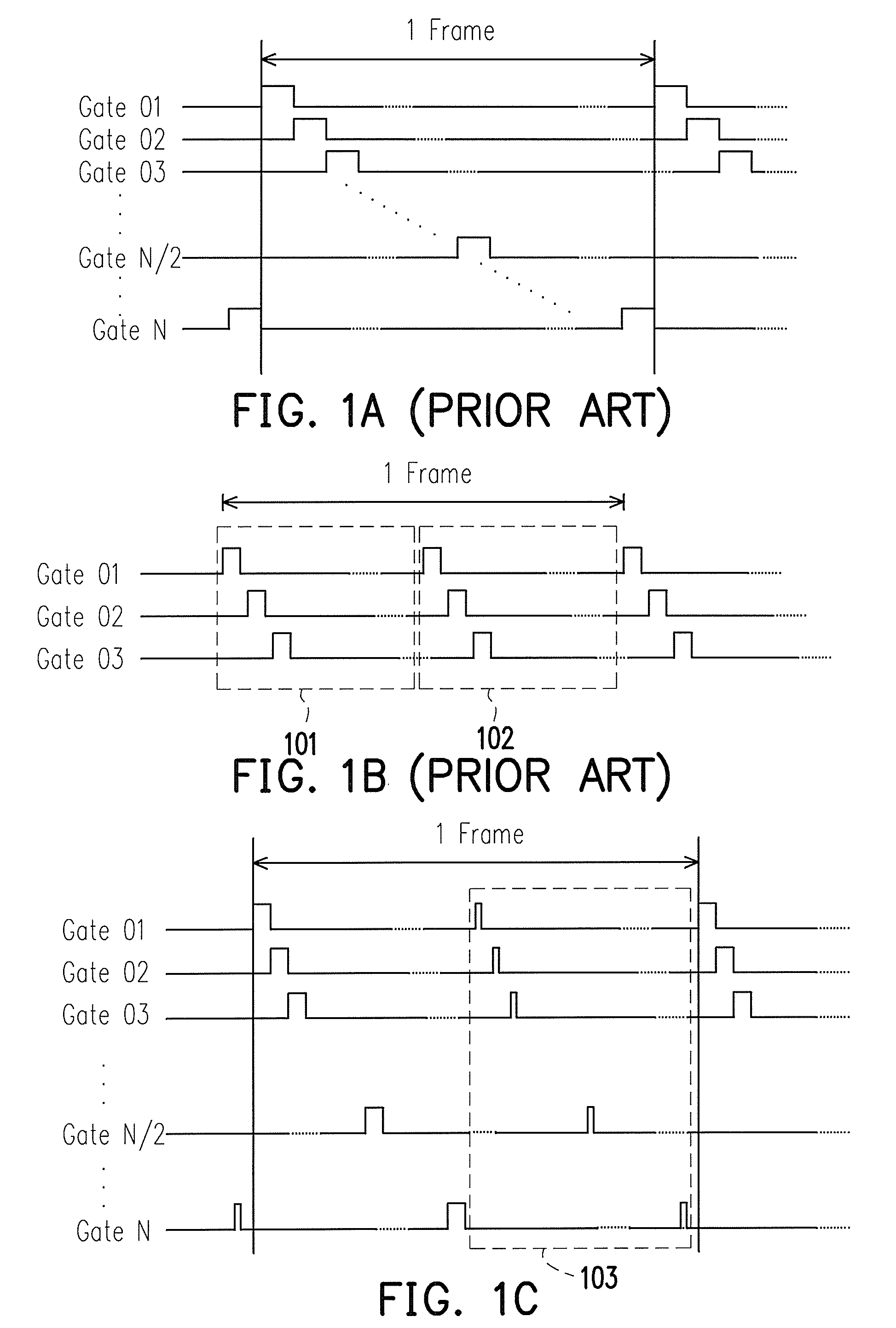
[0011]The present invention provides a gray insertion method of a liquid crystal display which may adjust various levels of gray insertion according to changes in the display images so as to promote image quality.
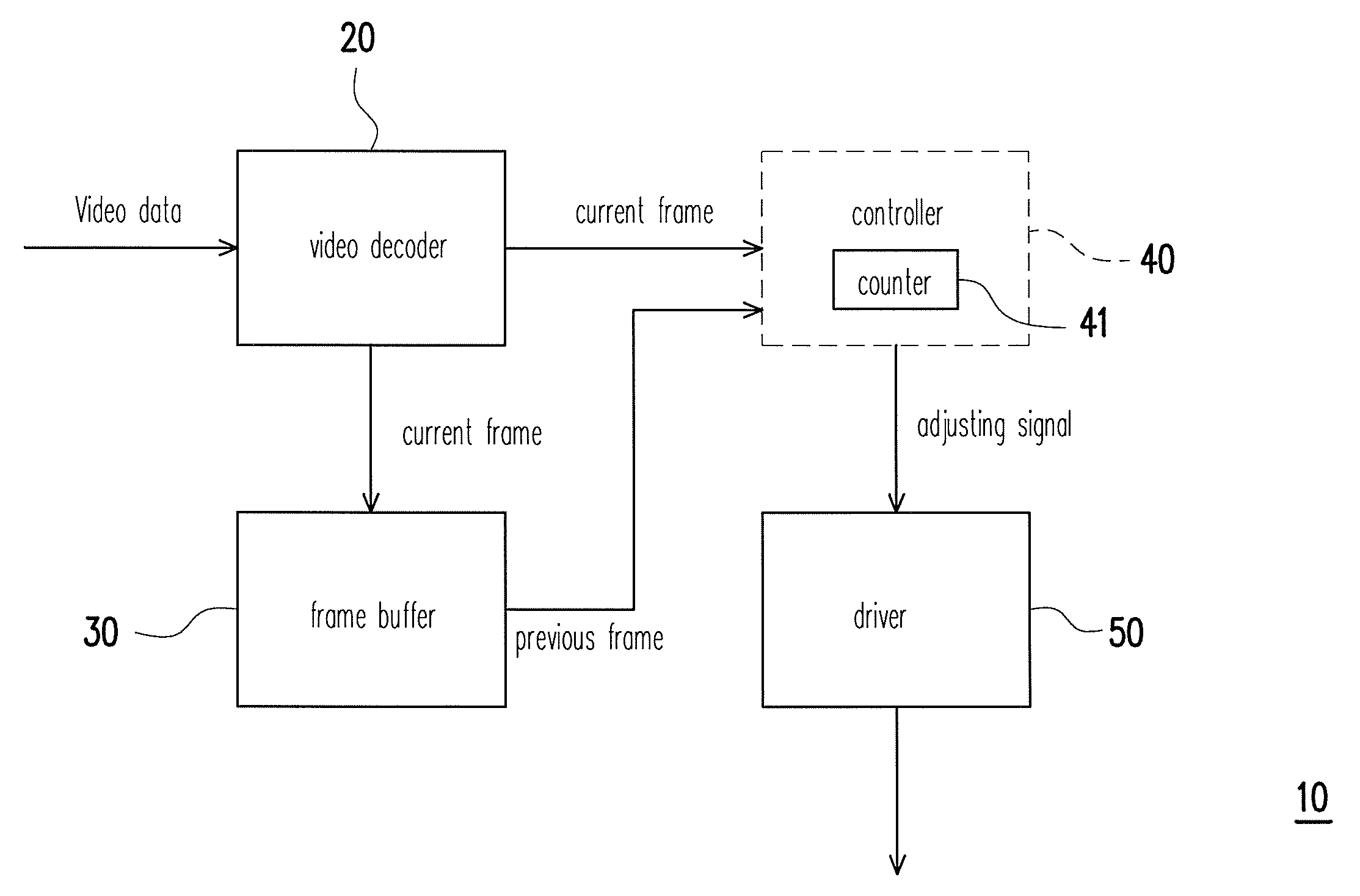
[0012]From another aspect, the present invention provides a driving circuit capable of analyzing a current frame to accordingly adjust charging time of a gray insertion image such that the problems of motion blur as well as low brightness are improved.
[0013]The present invention provides a gray insertion method of a liquid crystal display including analyzing whether a current frame belongs to a dynamic frame or a static frame. Furthermore, when the current frame belongs to a dynamic frame, charging time of a gray insertion image is extended. When the current frame belongs to a static frame, the charging time of a gray insertion image is shortened.
[0022]The present invention may analyze whether a current frame belongs to a dynamic frame or a static frame. When the current frame belongs to a dynamic frame, charging time of a gray insertion image is extended. When the current frame belongs to a static frame, the charging time of a gray insertion image is shortened. Therefore, quality of display images may be promoted.

Problems solved by technology

It should be noted that although the gray insertion technique may improve motion blur of a dynamic image, it may greatly decrease brightness of an image as well.
If the gray insertion technique is used in the LCD during the display of a static image, it results in low image contrast.
However, turning on and off the gray insertion function results in significant variance in the brightness level of the display image and hence causes great discomfort to the human eye.

Method used


Image

  • Driving cricuit and gray insertion method of liquid crystal display
  • Driving cricuit and gray insertion method of liquid crystal display
  • Driving cricuit and gray insertion method of liquid crystal display

Examples


Embodiment Construction

[0033]A conventional gray insertion method may improve motion blur of a dynamic image but may significantly reduce brightness of a dynamic image and a static image. In addition, turning on and off the gray insertion function results in significant variance in the brightness level of the display image and hence causes great discomfort to the human eye.

[0034]In light of the above, embodiments of the present invention provide a gray insertion method of an LCD. The method may analyze whether a current frame is a dynamic frame or a static frame. After the analysis is completed, if the current frame is a dynamic frame, charging time of a gray insertion image may be gradually extended so as to improve motion blur. In contrast, if the current frame is a static frame, the charging time of a gray insertion image may be gradually shortened so as to improve low brightness level of a display image. Furthermore, the abovementioned gradual control of the length of the charging time of a gray inser...


PUM


Abstract

A driving circuit and a gray insertion method of a liquid crystal display (LCD) are provided. The gray insertion method includes analyzing whether a current frame belongs to a dynamic frame or a static frame. When the current frame belongs to a dynamic frame, charging time of a gray insertion image is extended. When the current frame belongs to a static frame, the charging time of a gray insertion image is shortened. As a result, motion blur on the LCD can be reduced and image quality can be increased.

Description

CROSS-REFERENCE TO RELATED APPLICATION[0001]This application claims the priority benefit of Taiwan application serial no. 97137962, filed on Oct. 2, 2008. The entirety of the above-mentioned patent application is hereby incorporated by reference herein and made a part of this specification.BACKGROUND OF THE INVENTION[0002]1. Field of the Invention[0003]The present invention relates to a gray insertion technique of a liquid crystal display, and more particularly, to a gray insertion technique adaptively adjusting charging time of a gray insertion image to adjust gray insertion of various levels.[0004]2. Description of Related Art[0005]The liquid crystal display (LCD) adopts a hold-type display method so when the LCD displays a dynamic image, motion blur may occur. In general, a gray insertion technique is conventionally adopted to reduce motion blur. A brief illustration is first provided below on how the LCD panel is driven.[0006]A driving signal for the LCD panel mainly includes tw...

Claims


Application Information

Patent Timeline
Patent Type & Authority Applications(United States)
IPC IPC(8): G09G3/36G09G5/10
CPCG09G3/3611G09G2320/10G09G2320/0261G09G2310/061
Inventor LIN, HSIANG-TANYEN, SHIH-CHIEH
Owner CHUNGHWA PICTURE TUBES LTD
Learn More