Method and system to modelize resources and external data of a program for procedural language coding

a procedural language and external data technology, applied in the field of software development, can solve the problems of not providing a method to define the resources and data manipulated by a program, cannot be directly and obviously represented by uml 2.0, and cannot be used by uml to specify a data structure independently from its physical implementation,

Active Publication Date: 2010-04-08
IBM CORP
View PDF6 Cites 5 Cited by
  • Summary
  • Abstract
  • Description
  • Claims
  • Application Information

AI Technical Summary

Benefits of technology

[0021]It is an object of the invention to represent consistently with the high level UML design of logical data, the resources manipulated by a program to be coded into a procedural language and external data which is received from a program. As a result, this modelization will allow for systematic code generation of code in procedural language as it is possible today with UML for object oriented programs.

Problems solved by technology

However, the use of the tables in the database by a procedural program cannot be directly and obviously represented by UML 2.0.
However, this design documentation is close to the COBOL code, it cannot be used by UML to specify a data structure independently from its physical implementation.
These techniques do not provide a method to define the resources and data manipulated by a program in a way that is consistent with the UML design models which capture logical definitions of both program and data.
Since relationships can only be drawn from a class to another class in a UML class diagram, it is not possible with this representation to use relationships in order to describe the “participating tables” of a program as done with prior art [2].
However, it does not allow the capturing of some important information about a program: it does not provide a method to capture all the resources that a program manipulates, such as files or relational tables.
This is a limitation of the method since a significant amount of classes defined in an architectural class diagram are designed to describe data definition and will be used as persisted data, such as files, tables of a database (hierarchical or relational) message queues, etc.
Capturing only the data that programs share with other programs is not enough.
Thus this method lacks completeness to fully describe the data that the program manipulates, when such information is likely to be already captured in the class diagram.
Doing this is not satisfactory for several reasons:the logical definition of business data needs to be preserved and separated from its physical description.

Method used


Image

  • Method and system to modelize resources and external data of a program for procedural language coding
  • Method and system to modelize resources and external data of a program for procedural language coding
  • Method and system to modelize resources and external data of a program for procedural language coding

Examples


Embodiment Construction

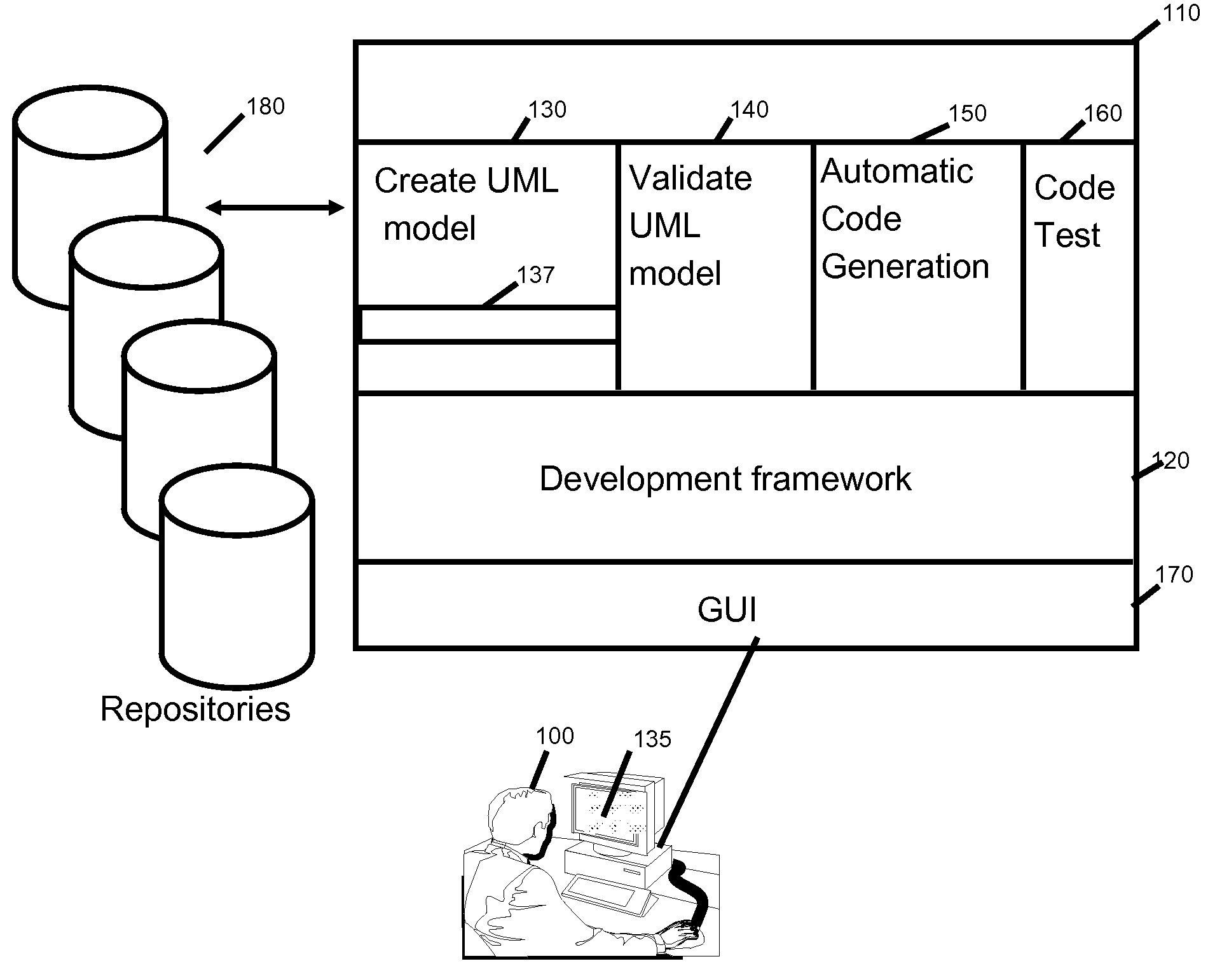
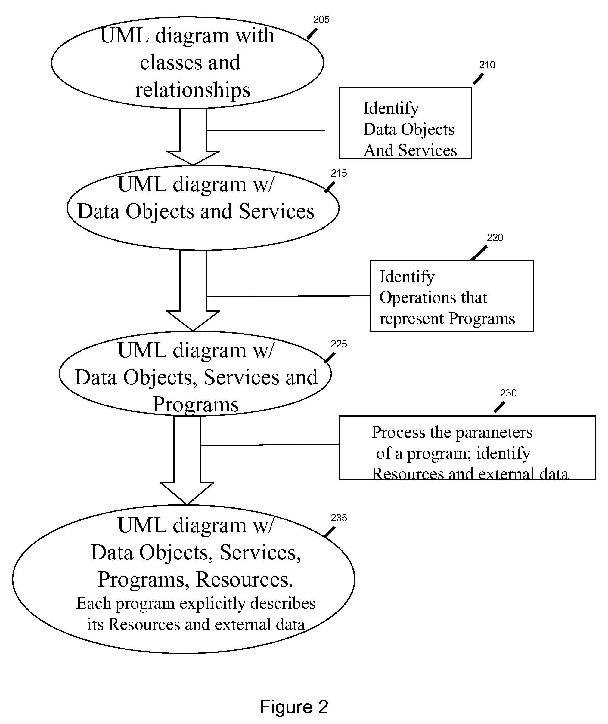
[0061]FIG. 1 is the system environment of the method of the preferred embodiment. The developer (100) who wants to create procedural programming code, uses a development framework (120) on his computer and a UML design tool (130) for designing programs with graphical user interface (137), for validating the model (140), for creating code (150), automatically in the preferred embodiment, and testing it (160) using a code test environment. Repositories (180) storing models, code elements, scripts etc. . . . are accessed by these design tools. A UML class diagram (135) representing the classes and their relationships is displayed on the console of the developer. These classes will be used by the components of the application. With the method of the preferred embodiment, the developer can extend the class diagram and identify the operation of a class, which is supposed to represent a program. The parameters of the operation will capture the data manipulated by the program. The developer...


PUM


Abstract

A method and system to represent in UML the resources and external data manipulated by a program to be coded in a procedural language is disclosed. The usual UML class diagram is enhanced with two new stereotypes “Program” and “Data Object”. The program stereotypes applied to an operation and its parameters describe the data manipulated, through the logical definition provided by the Data Object. This model will be enhanced in order to introduce classes on which the Resource stereotype is applied. These classes will be connected to the appropriate logical data definition (the Data Object) and used as parameter types of the operation instead of the Data Object. A second set of stereotypes will be applied to the Resource classes to indicate the physical type of the resource (a file, table etc. . . . ) and its characteristics. Parameters that point to a DataObject or a primitive type will be considered as external data.

Description

FIELD OF THE INVENTION[0001]The present invention generally relates to software development; more particularly, the invention aims at representing in a design model of a program that will be coded in a procedural language such as COBOL, resources and external data using the UML graphical modelization.BACKGROUND OF THE INVENTION[0002]To develop software applications in a procedural language code such as COBOL, it appears relevant to create design models including a representation for data manipulated by the programs of the application. There are three categories of data that a program manipulates: (1) the resources of a program that can be files, tables, message queues etc. . . . , (2) they're are data that the program manipulates and which come from external sources. The external data are manipulated by a program, they are the parameters that the program can accept or exchange and which are passed in memory by one other program which is called. The representation of an external data...

Claims


Application Information

Patent Timeline
Patent Type & Authority Applications(United States)
IPC IPC(8): G06F9/44
CPCG06F8/10
Inventor DANGEVILLE, NICOLASPONIN, JOHAN
Owner IBM CORP
Why Eureka
Try Eureka