Method and arrangement for maintaining a diesel particulate filter in a diesel engine exhaust system

a technology for diesel engines and particulates, which is applied in the direction of machines/engines, electrical control, electric control of exhaust treatment, etc., can solve the problems of engine backpressure, engine cracking or melting of dpf, and soot burning in an uncontrolled manner, and achieve the effect of increasing engine backpressur

Active Publication Date: 2010-04-15
VOLVO LASTVAGNAR AB
View PDF10 Cites 17 Cited by
  • Summary
  • Abstract
  • Description
  • Claims
  • Application Information

AI Technical Summary

Benefits of technology

[0002]In diesel engines, it is now typical to use a DPF downstream of the engine to filter particulate from the engine exhaust. If too much soot collects in the DPF, the soot can burn in an uncontrolled manner and may crack or melt the DPF. This phenomenon is sometimes referred to as a “runaway” or uncontrolled regeneration. Other problems can result from excessive soot accumulation in the DPF as well, such as an increase in engine backpressure, which can have an adverse effect on engine operation and affect fuel consumption.

Problems solved by technology

If too much soot collects in the DPF, the soot can burn in an uncontrolled manner and may crack or melt the DPF.
Other problems can result from excessive soot accumulation in the DPF as well, such as an increase in engine backpressure, which can have an adverse effect on engine operation and affect fuel consumption.
Two main causes for non-uniform soot distribution are high flow velocity through the DPF, such as often occurs during highway driving, and so-called passive regeneration, which occurs when NO2 in the exhaust gas oxidizes the soot.
In other words, in certain conditions, the pressure drop measurements may tend to underestimate actual soot loading on parts of the DPF, which can lead to damage to the DPF.

Method used


Image

  • Method and arrangement for maintaining a diesel particulate filter in a diesel engine exhaust system
  • Method and arrangement for maintaining a diesel particulate filter in a diesel engine exhaust system
  • Method and arrangement for maintaining a diesel particulate filter in a diesel engine exhaust system

Examples


Embodiment Construction

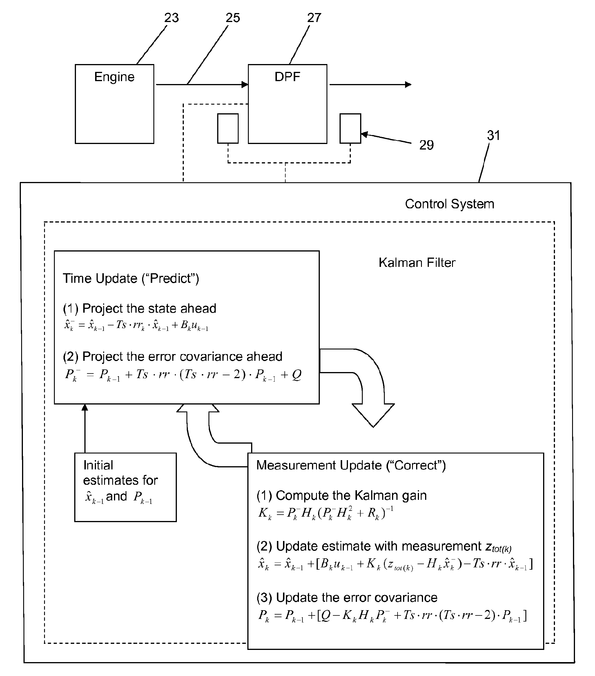
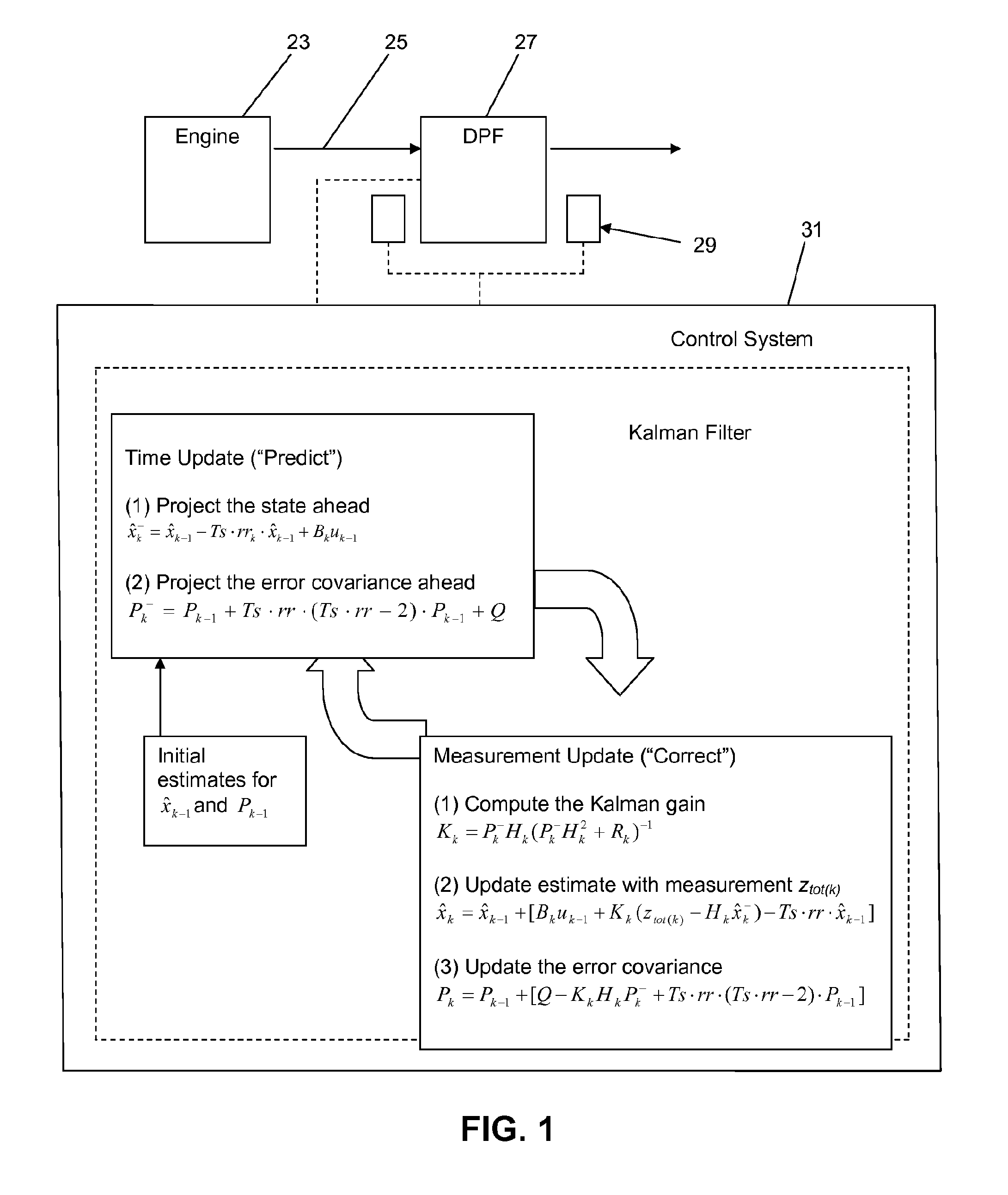
[0014]A diesel engine system 21 according to an embodiment of the present invention shown in FIG. 1 and comprises a diesel engine 23 and an exhaust line 25 including a DPF 27 downstream of the engine cylinders. A sensor arrangement 29 that ordinarily includes differential pressure (delta-P) sensor measures pressure at an inlet and an outlet of the DPF 27. A heating element or device (not shown) is disposed in or upstream of the DPF 27 to raise the temperature of the exhaust gas flow during active regeneration. The sensor arrangement 29 also typically comprises monitors for monitoring temperature of the exhaust gas flow, typically at least in the DPF, often upstream and downstream of the DPF, as well.

[0015]A controller 31 is provided. The controller 31 receives signals from the delta-P sensor and the temperature monitors, processes the signals, and, in response to the signals, determines whether active regeneration should be triggered or, if triggered, whether it should be stopped. I...


PUM


Abstract

A method and apparatus for maintaining a diesel particulate filter (DPF) is provided. A pressure drop across the DPF is measured and an initial estimate of soot loading in the DPF is provided to a recursive filter. Using the recursive filter, the initial estimate of soot loading is updated in view of the measured pressure drop to provide an updated estimate of soot loading in the DPF. Active regeneration of the DPF is triggered when an earliest one of at least one triggering condition occurs, the updated estimate of soot loading reaching a predetermined value being one of the at least one triggering condition.

Description

BACKGROUND AND SUMMARY[0001]The present invention relates generally to diesel engines with exhaust systems comprising diesel particulate filters (DPF) and, more particularly, to methods and arrangements for triggering and stopping active regeneration in DPFs.[0002]In diesel engines, it is now typical to use a DPF downstream of the engine to filter particulate from the engine exhaust. If too much soot collects in the DPF, the soot can burn in an uncontrolled manner and may crack or melt the DPF. This phenomenon is sometimes referred to as a “runaway” or uncontrolled regeneration. Other problems can result from excessive soot accumulation in the DPF as well, such as an increase in engine backpressure, which can have an adverse effect on engine operation and affect fuel consumption.[0003]To avoid aforementioned problems such as runaway regenerations, it is common to periodically clean the DPF by burning off the soot, through a so-called active regeneration by O2 oxidation, in a control...

Claims


Application Information

Patent Timeline
Patent Type & Authority Applications(United States)
IPC IPC(8): F01N9/00F01N3/023
CPCF01N3/027F01N9/002F01N2560/06F01N2560/08Y02T10/47F02D41/029F02D2041/1417F02D2200/0812F01N2900/1606Y02T10/40
Inventor TAI, CHUNSVENSSON, KENTH I.
Owner VOLVO LASTVAGNAR AB
Why Eureka
Try Eureka