Service apparatus for a transportation means

a technology for transportation means and service equipment, applied in vehicle heating/cooling devices, aircraft crew accommodation, light support devices, etc., can solve problems such as old-fashioned appearance and conventional design, and achieve the effects of reducing the current consumption of illumination devices, compact design, and favourable current consumption

Inactive Publication Date: 2010-04-15
AIRBUS OPERATIONS GMBH
View PDF7 Cites 39 Cited by
  • Summary
  • Abstract
  • Description
  • Claims
  • Application Information

AI Technical Summary

Benefits of technology

[0007]According to a first aspect of the invention, a first component in the form of an air shower with an air inlet and at least one air outlet and a component in the form of an illumination device are arranged essentially centrically in relation to each other. One of the two components encloses the other component essentially in a ring-shaped manner. This results in the air shower and the illumination device forming an integral design unit that requires significantly less design space than a forced-air nozzle and an illumination device that are designed so as to be separate of each other. As desired, two different design options for such service apparatuses are available. On the one hand it is possible to provide the air shower as a central component while it is enclosed in a ring-shaped manner by an illumination device. This provides an advantage in that air showers that are readily available in the market may be integrated in the service apparatus according to the invention, and may be enclosed by suitable illumination devices.
[0015]Furthermore, such a closing device would not have to be positioned directly in front of light emission apertures of an illumination device, but instead it could also be very advantageous if the closing device were to be integrated in the light-guide fibre bundle of a central illumination unit such that already the light guide to the illumination device is interrupted or weakened. Consequently, the closing device could be arranged behind a service duct surface or the like so that it is completely invisible to a user; an arrangement which improves the visual appearance of the illumination device.

Problems solved by technology

Apart from taking up design space, such an arrangement is associated with a further, subjective, disadvantage in that it has a conventional and old-fashioned appearance.

Method used


Image

  • Service apparatus for a transportation means
  • Service apparatus for a transportation means
  • Service apparatus for a transportation means

Examples


Embodiment Construction

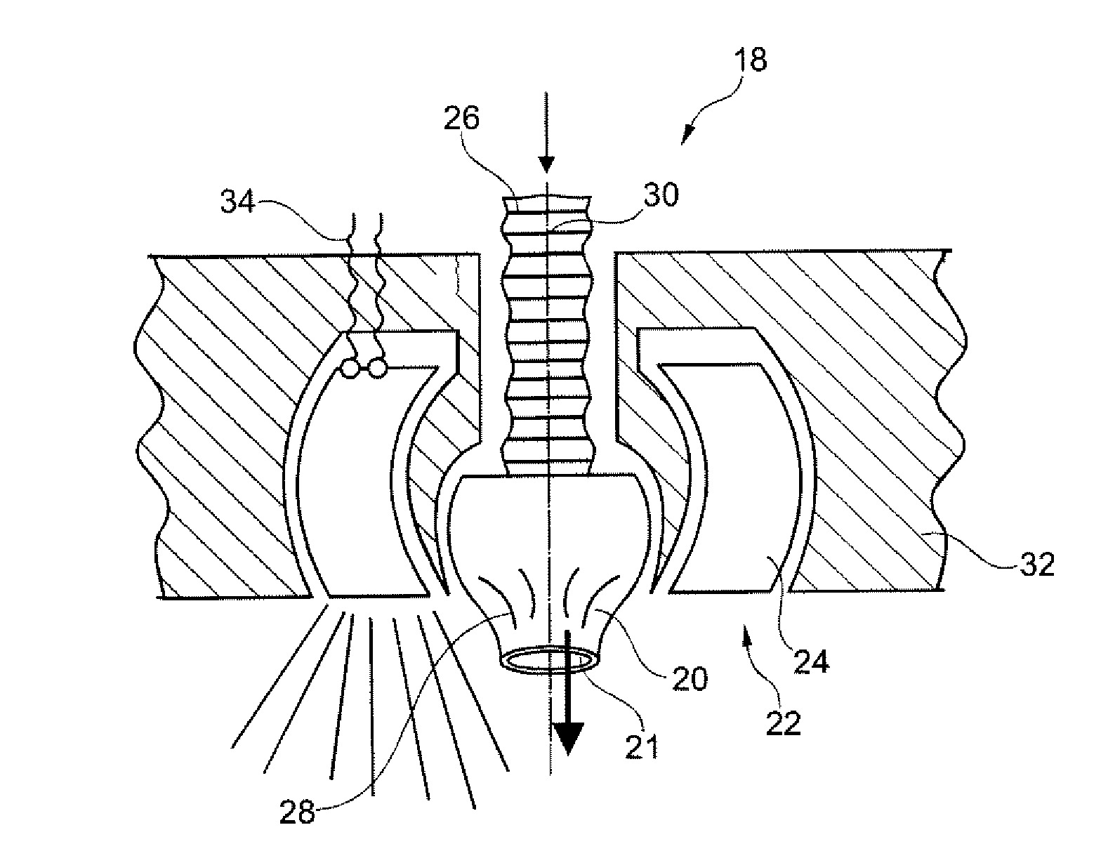
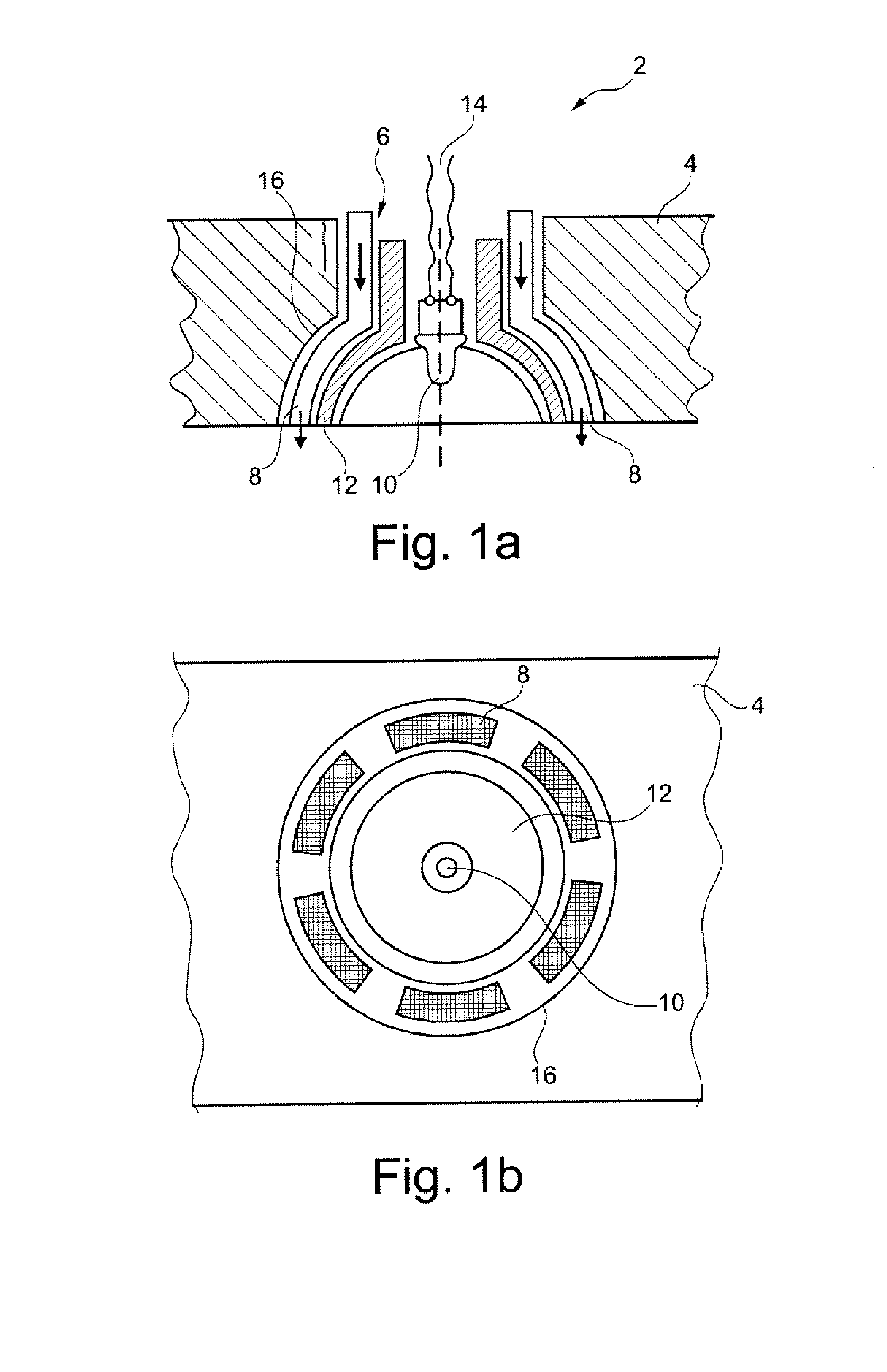
[0024]FIG. 1a diagrammatically shows a lateral section of the service apparatus 2 according to the invention, which service apparatus 2 is accommodated in a housing 4 and comprises an air shower 6 with several air outlets 8 that essentially are positioned in a ring-shaped manner around an illumination device 10. Between the air outlets 8 and the illumination device 10 a lamp housing 12 is arranged which together with the illumination device 10 forms a reading light that provides a relatively pronouncedly-bundled light ray.

[0025]In the shown first exemplary embodiment of the service apparatus 2 according to the invention the illumination device 10 is designed as a light-emitting diode which by means of cabling 14 is connected to an electrical power network or a corresponding control device (not shown) which switches the illumination device 10 on or off directly by means of switches or by way of a databus or a network.

[0026]A horizontal projection of the underside of the service appar...


PUM


Abstract

A service apparatus for a transportation means comprises a first component in the form of an air shower with an air inlet and at least one air outlet, and a second component in the form of an illumination device. The first component and the second component are arranged essentially centrically in relation to each other, wherein one of the two components encloses the other component essentially in a ring-shaped manner. In this way an integral reading light with a forced-air nozzle, or an integral forced-air nozzle with a reading light, is implemented that uses little design space.

Description

CROSS-REFERENCE TO RELATED APPLICATIONS[0001]This application claims the benefit of the filing date of U.S. Provisional Patent Application No. 61 / 195,813 filed Oct. 10, 2008, the disclosure of which is hereby incorporated herein by reference.BACKGROUND OF THE INVENTION[0002]The invention relates to a service apparatus for a transportation means, comprising an air shower with an air inlet and at least one air outlet and an illumination device. The invention further relates to the use of such a service apparatus in a transportation means, as well as to an aircraft comprising at least one such service apparatus.[0003]In modern transportation means it is very common to provide service units in service ducts in order to provide passengers at their locations with convenience elements and safety devices. Such service units also include service apparatuses, which in the context of the present invention refers to apparatuses in which an illumination device for reading, as well as an air show...

Claims


Application Information

Patent Timeline
Patent Type & Authority Applications(United States)
IPC IPC(8): B64D13/00B60Q1/00F21S8/10G02B6/04B60H1/34
CPCB60H1/34B60Q3/001B60Q3/004B60Q3/0253B60Q2500/20B64C2027/8236G02B6/0008B64D47/02B64D2011/0053B64D2013/003F21V33/0092F21W2101/06F21Y2101/02B64D13/00B60Q3/44B60Q3/64B60Q3/85F21Y2115/10F21W2107/30
Inventor HOGH, ROBERTMUELLER, JOCHEN
Owner AIRBUS OPERATIONS GMBH
Why Eureka
Try Eureka