Prosthetic device for knee joint and methods of implanting and removing same

a knee joint and prosthesis technology, applied in the field of knee joint prosthesis, can solve the problems of multiple cutting tools, long bone preparation time, and difficulty in keel of a conventional prosthesis devi

Active Publication Date: 2010-04-15
MAKO SURGICAL CORP
View PDF7 Cites 75 Cited by
  • Summary
  • Abstract
  • Description
  • Claims
  • Application Information

AI Technical Summary

Problems solved by technology

The large, central keel of a conventional prosthetic device can create difficulties during implantation.
Forming this deep void can cause bone preparation time to be longer than desired, and require multiple cutting tools.
Moreover, the large keel can cause fracture of bone during implantation, such as when the void is not sufficiently wide and / or deep.
The large keel also can create difficulties during revision, e.g., the removal of the prosthetic device from the bone to allow for its replacement with a new prosthetic device.
Also, the keel itself may cause removal of a relatively large amount of bone when the prosthetic device is removed from the bone, especially when cement is used to join the keel to the bone.
The rim itself typically does not sufficiently enhance the strength and stiffness of the prosthetic device.
The intersection of those substantially planar surfaces can result in thin material cross-sections, concentrating and increasing stresses, which can lead to failure of the prosthetic device.
Moreover, because the prosthetic device must be sufficiently thick at the intersection of substantially planar sections to decrease the likelihood of failure, other areas of the prosthetic device may be thicker than necessary, thus requiring more than an optimal amount of bone removal for implantation.

Method used


Image

  • Prosthetic device for knee joint and methods of implanting and removing same
  • Prosthetic device for knee joint and methods of implanting and removing same
  • Prosthetic device for knee joint and methods of implanting and removing same

Examples


Embodiment Construction

[0051]Presently preferred embodiments of the invention are illustrated in the drawings. An effort has been made to use the same or like reference numbers throughout the drawings to refer to the same or like parts.

Overview

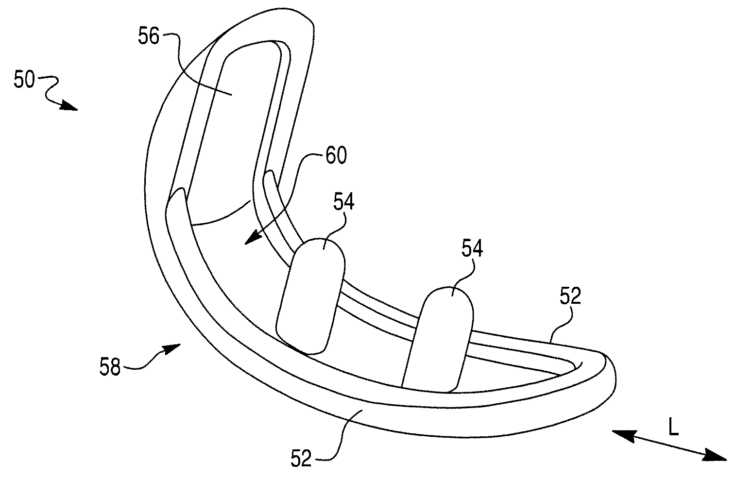
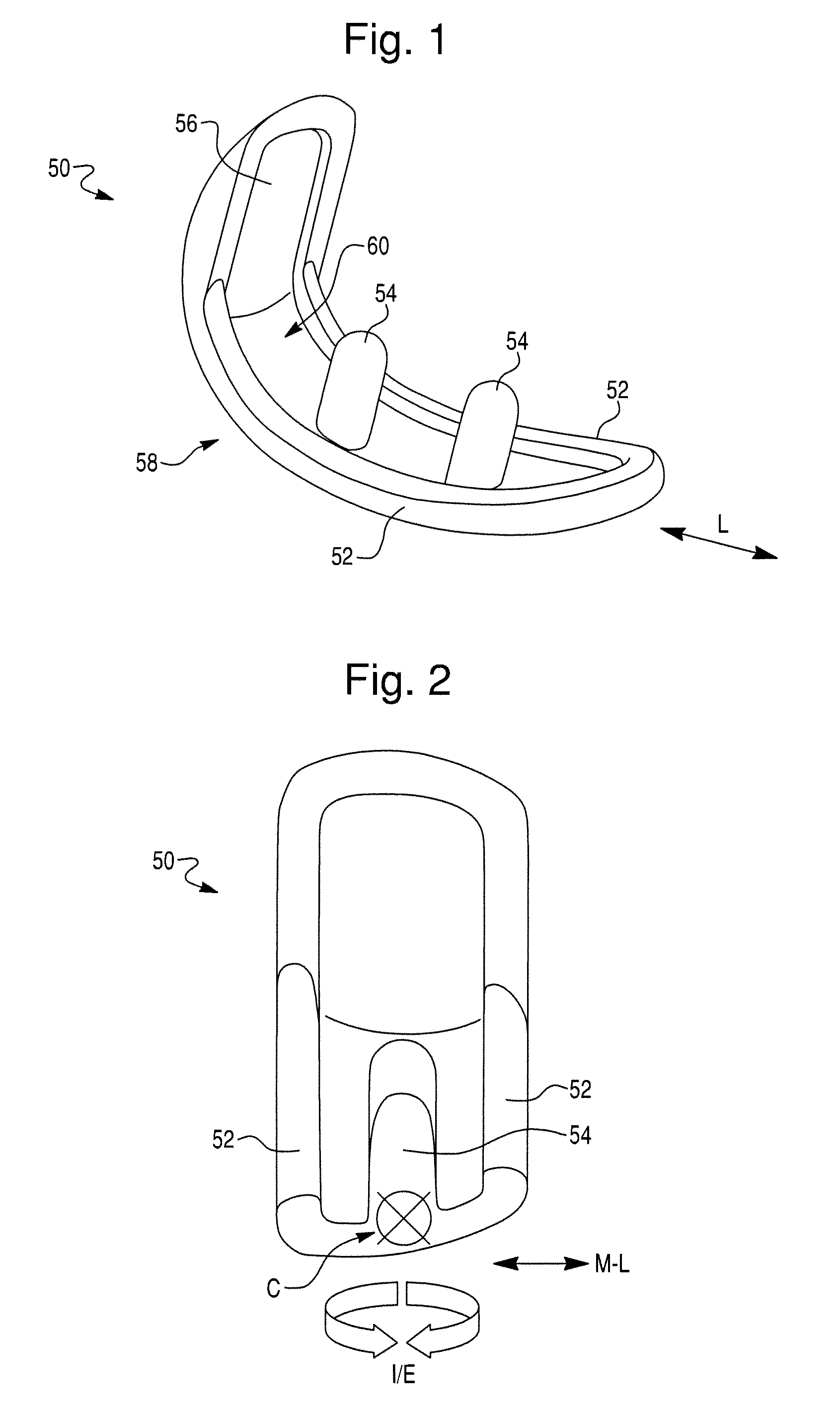
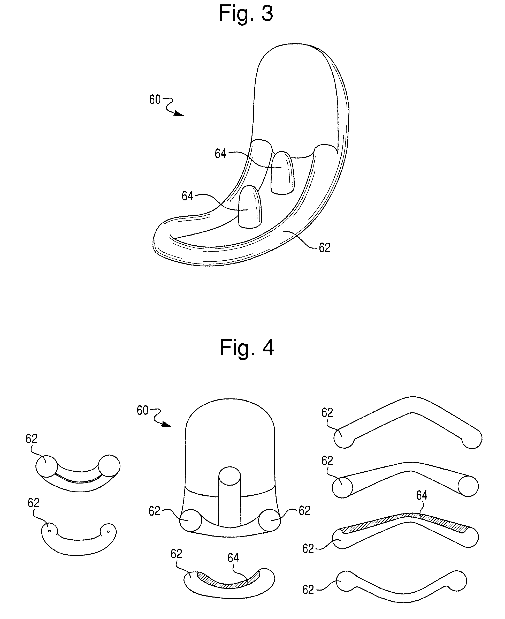
[0052]A prosthetic device for a knee joint according to the present invention preferably is a unicompartmental component for replacement of a portion of the knee joint (such as a compartment of the femur), however, it also could be a total knee component. The prosthetic device also could be, for example, a patellofemoral component, a tibial baseplate, or a tibial inlay. The prosthetic device preferably includes a body portion for attachment to a bone of the knee joint and one or more keels.

[0053]The body portion of the prosthetic device can be formed from materials that are conventional in the art, or of other materials. The body portion can have a bearing surface that can be configured to replace at least a portion of the bone of the knee joint. The bearing surface...


PUM


Abstract

A prosthetic device for a knee joint includes a body portion and a first keel. The body portion attaches to a bone of a knee joint. The body portion can have a bearing surface configured to replace at least a portion of the bone and an implantation surface configured to face the bone upon implantation. The first keel can be configured to be inserted into a corresponding first keel void formed in the bone. The first feel can be configured to project outwardly from the implantation surface by an amount sufficient to inhibit movement of the body portion relative to the bone in both medial and lateral directions upon insertion into the first keel void. The first keel can extend along a longitudinal direction of the body portion and is offset from a longitudinal centerline of the body portion. Methods of implanting and removing the prosthetic device are also provided.

Description

CROSS-REFERENCE TO RELATED PATENT APPLICATIONS[0001]This application claims priority to U.S. Provisional Patent Application Ser. No. 61 / 194,954, filed on Oct. 2, 2008, which is hereby incorporated by reference in its entirety.BACKGROUND OF THE INVENTION[0002]1. Field of Invention[0003]The present invention relates to a prosthetic device for a knee joint, particularly a prosthetic device for a knee joint having a body portion and a keel, and methods of implanting and removing the same.[0004]2. Description of Related Art[0005]Prosthetic devices for knee joints, e.g., knee implants, typically have structures on the bone interface surface to facilitate attachment of the prosthetic device to the bone of the knee joint. For example, it is common for a prosthetic device to have one or more pegs and a keel extending outwardly from a longitudinal axis or centerline of the bone interface surface. Such a keel typically is large and projects a significant length from the bone interface surface ...

Claims


Application Information

Patent Timeline
Patent Type & Authority Applications(United States)
IPC IPC(8): A61F2/38
CPCA61F2/3859A61F2/3877A61F2/389A61F2002/30879A61F2002/4619A61F2002/30884A61F2002/30892A61F2002/3895A61F2002/30881
Inventor OTTO, JASON KARL
Owner MAKO SURGICAL CORP
Why Eureka
Try Eureka