Intervertebral implant with keel

a technology of intervertebral implants and keels, applied in the field of disc replacement, can solve the problems of high force applied in the cutting direction, inability to mill, and slip or bend of drills during drilling, so as to prevent bone growth and prevent bone growth

Active Publication Date: 2010-08-26
CENTINEL SPINE LLC
View PDF104 Cites 55 Cited by
  • Summary
  • Abstract
  • Description
  • Claims
  • Application Information

AI Technical Summary

Benefits of technology

[0007]Also in accordance with a disclosed embodiment, an intervertebral implant component of an intervertebral implant includes an outer surface for engaging an adjacent vertebra and an inner surface. A keel extends from the outer surface and is designed to be disposed in a slot provided in the adjacent vertebra. An anterior shelf is also provided at an anterior end of the outer

Problems solved by technology

However, where a chisel cut is made using a chisel and a mallet, quite high forces are applied in direction of the cut.
With drilling, lesser forces are applied, but the drill can slip of or bend during drilling.
With mill

Method used


Image

  • Intervertebral implant with keel
  • Intervertebral implant with keel
  • Intervertebral implant with keel

Examples


Embodiment Construction

Materials

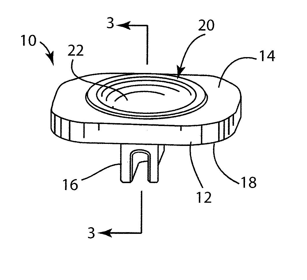
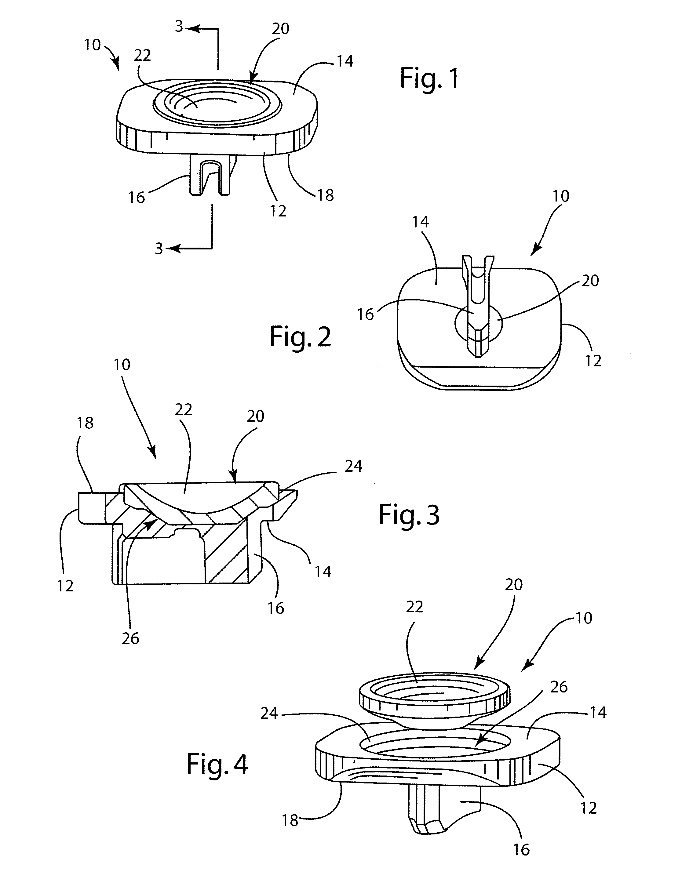
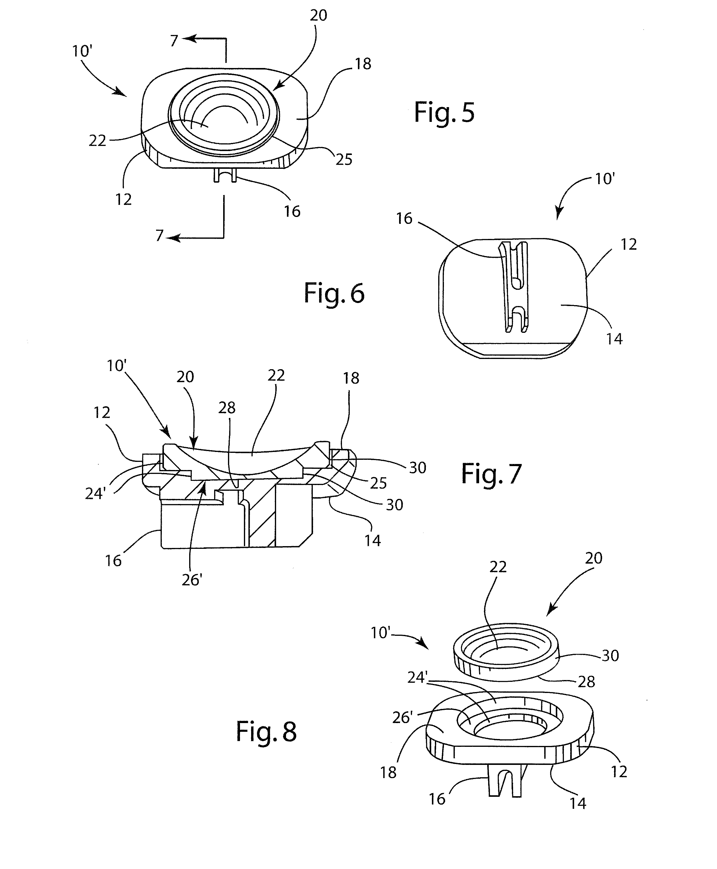
[0041]With reference now to the drawings in which like numerals represent like elements throughout the views, a first component 10 of an intervertebral implant for total disc replacement according to the present invention is depicted in FIGS. 1-4. The implant including component 10 is primarily designed for insertion between adjacent vertebrae from an anterior direction. Thus, reference will sometimes be made to anterior and posterior directions for convenience. However, it will be appreciated that insertion from other directions is possible, and hence the referenced directions would thus be similarly changed. In addition, terms such as front / back, forward / rearward, left / right and top / bottom may be used to identify directions as depicted in the figures and / or as the implant is used relative to any insertion direction, even though the “front” may be facing anteriorly or posteriorly depending on the direction of insertion used. Thus, these terms are used for illustration purp...


PUM

PropertyMeasurementUnit
Shapeaaaaaaaaaa
Depthaaaaaaaaaa
Frictionaaaaaaaaaa

Abstract

An intervertebral implant component of an intervertebral implant includes an outer surface for engaging an adjacent vertebra and an inner surface. A keel extends from the outer surface and is designed to be disposed in a slot provided in the adjacent vertebra. This keel extends in a plane which is non-perpendicular to the outer surface; and preferably there are two of the keels extending from the outer surface which are preferably offset laterally from one another. In another embodiment, an anterior shelf is provided at an anterior end of the outer surface, and this anterior shelf extends vertically away from the inner surface in order to help prevent bone growth from the adjacent vertebra towards the inner surface. Further in accordance with disclosed embodiments, various materials, shapes and forms of construction of the component and/or keel provide various benefits.

Description

BACKGROUND OF THE INVENTION[0001]Historically, when it was necessary to completely remove a disc from between adjacent vertebrae, the conventional procedure was to fuse the adjacent vertebrae together. This “spinal fusion” procedure, which is still in use today, is a widely accepted surgical treatment for symptomatic lumbar and cervical degenerative disc disease.[0002]More recently, there have been important developments in the field of disc replacement, namely disc arthoplasty, which involves the insertion of an artificial intervertebral disc implant into the intervertebral space between adjacent vertebrae. Such a disc implant allows limited universal movement of the adjacent vertebrae with respect to each other. The aim of total disc replacement is to remove pain generation (caused by a degenerated disc), restore anatomy (disc height), and maintain mobility in the functional spinal unit so that the spine remains in an adapted sagittal balance. Sagittal balance is defined as the eq...

Claims


Application Information

Patent Timeline
IPC IPC(8): A61F2/44A61B17/00
CPCA61B17/14A61B17/148A61B17/15A61B17/1604A61B17/1671A61F2/4425A61F2/4684A61F2002/30056A61F2002/30112A61F2002/30331A61F2002/30383A61F2002/30448A61F2002/30485A61F2002/30507A61F2002/30576A61F2002/30594A61F2002/30604A61F2002/30677A61F2002/30884A61F2002/30891A61F2002/30894A61F2002/30897A61F2002/30899A61F2002/30901A61F2002/30902A61F2002/30904A61F2002/30932A61F2002/443A61F2002/449A61F2220/0025A61F2220/0033A61F2220/005A61F2230/0004A61F2250/0032A61F2310/00023A61F2310/00161A61F2310/00179A61F2310/00449A61F2310/00574A61F2310/0058A61F2310/0088A61F2310/0097A61B17/141A61B17/144Y10T83/9454A61F2220/0008A61F2002/30878A61B2017/0256A61F2/4611A61F2002/4627A61F2/442A61F2/44
Inventor BERTAGNOLI, RUDOLFHANSON, SHAUNRICHTER, JOERNFURDA, JOHNHALLER, FABIANGERBER, DAVIDBERGER, ROGERKAUFMANN, STEFANIE
Owner CENTINEL SPINE LLC
Why Eureka
Try Eureka