Knee prosthesis

a technology for tibia and tibia, which is applied in the field of tibial components, can solve the problems of inability to remove the tibial platform and the stem or keel, titanium or cobalt-chromium alloy shards and swarfs undetectedly introduced into the body, and substantial damage to the surrounding bone of the tibia, so as to encourage growth and fixation of the tibia

Inactive Publication Date: 2006-06-29
CORIN
View PDF30 Cites 54 Cited by
  • Summary
  • Abstract
  • Description
  • Claims
  • Application Information

AI Technical Summary

Benefits of technology

[0009] According to a third aspect of the invention, there is provided a tibial component for a cementless knee prosthesis, the tibial component comprising a tibial platform and a wedge-shaped keel for connecting the tibial platform to a tibia, at least a portion of the tibial platform having a coating of osteoconductive material for encouraging growth and fixation of the tibia to the tibial platform.

Problems solved by technology

An initial problem associated with the device of U.S. Pat. No. 6,258,127B1 is that the distal edge of the anchoring plate is a cutting edge, intended to allow the plate to be forcibly driven into the prepared capsule of the tibia.
Further problems associated with all known tibial components are the difficulty of removal of both the tibial platform and the stem or keel when, for example, a revision is required.
The tibial platform is typically removed by sawing the platform from the stem or anchoring element, resulting in titanium or cobalt-chromium alloy shards and swarf being undesirably introduced into the body during the surgical procedure.
Once the tibial platform is finally removed, it can be extremely difficult and time consuming to then remove the stem or keel, often resulting in substantial damage to the surrounding bone of the tibia.
Even when utilising a shield-type anchoring element in an arrangement such as suggested in U.S. Pat. No. 6,258,127B1, it is extremely problematic to form cuts on opposite sides of the anchoring element, which intersect and thus allow the anchoring element to be simply lifted out of the tibia.

Method used


Image

  • Knee prosthesis
  • Knee prosthesis
  • Knee prosthesis

Examples


second embodiment

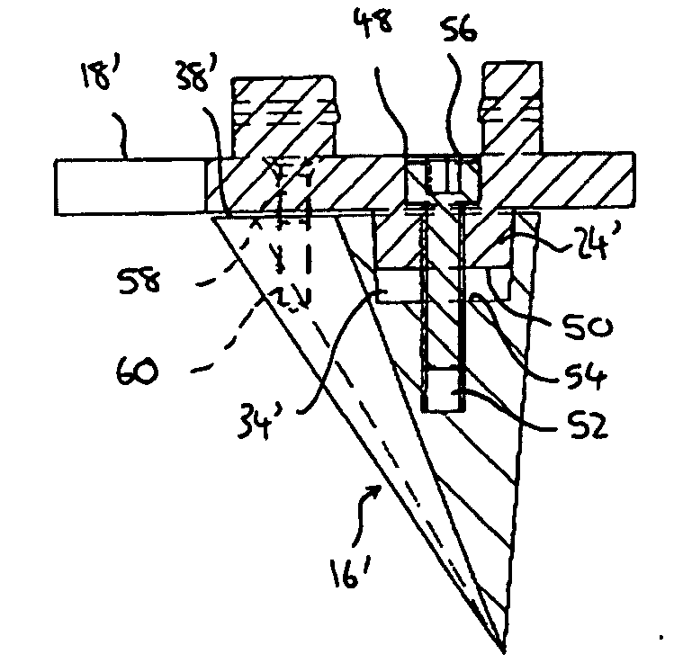
[0054] Referring to FIGS. 10 and 11, a tibial component is shown. Like references refer to like parts, and further description will be omitted.

[0055] In this embodiment, connecting spigot 24′ on inferior surface 20′ of tibial platform 14′ includes an axial through-hole 48 which opens out on superior surface 18′ of the tibial platform 14′ and distal end 50 of the spigot 24′. Socket 34′, provided in the upper surface 38′ of keel 16′ and dimensioned as previously described for accepting the connecting spigot 24′ as an interference fit, also includes a screw-threaded opening 52 in its bottom surface 54. A, typically anti-vibration, screw-threaded fastener 56 is thus be receivable in the axial through-hole 48 of the tibial platform 14′ and is engageable in the opening 52 in the bottom 54 of the socket 34′, thereby securely and releasably engaging the tibial platform 14′ and the keel 16′. This arrangement minimises the risk of loosening occurring between the connecting spigot 24′ and the ...

third embodiment

[0059] Referring to FIG. 12, a tibial component is shown. Again, like references refer to like parts, and further description will be omitted.

[0060] In this case, connecting spigot 24″ is provided on upper surface 38″ of keel 16″, and socket 34″, dimensioned as previously described for accepting the connecting spigot 24″ as an interference fit, is provided in inferior surface 20″ of tibial platform 14″. The connecting spigot 24″ is formed with a groove 62 adjacent to its distal end 50″. Preferably, the groove 62 is endless.

[0061] A through-hole 64 is formed through the anterior edge 66 of the tibial platform 14″ and breaks out into the socket 34″. The through-hole 64 is threaded to allow a, typically anti-vibration, screw threaded fastener 68 to be inserted into the tibial platform 14″. When the connecting spigot 24″ is received in the socket 34″, the fastener 68 projects into the groove 62 of the connecting spigot 24″, thus preventing separation of the tibial platform 14″ and the ...


PUM


Abstract

A tibial component for a knee prosthesis comprises a tibial platform and a wedge-shaped keel which is disengageably attachable to the tibial platform. The tibial platform has a superior surface for supporting a fixed or mobile bearing component and an inferior surface which, when the tibial platform and the keel are engaged with each other, is spaced from an upper surface of the keel. A knee prosthesis having the tibial component , and a system are also provided.

Description

BACKGROUND OF THE INVENTION [0001] The present invention relates to a knee prosthesis, and more particularly to a tibial component for a knee prosthesis. [0002] It is known from U.S. Pat. No. 6,258,127 B1 to provide a tibial component, which has a tibial platform and an anchoring element in the form of a plate or shield. The anchoring element is flat except for the provision of screw receiving holes to enable connection of the tibial platform to the anchoring plate. [0003] An initial problem associated with the device of U.S. Pat. No. 6,258,127B1 is that the distal edge of the anchoring plate is a cutting edge, intended to allow the plate to be forcibly driven into the prepared capsule of the tibia. Splitting of the tibia could therefore occur during implantation if great care is not taken by the surgeon. [0004] Further problems associated with all known tibial components are the difficulty of removal of both the tibial platform and the stem or keel when, for example, a revision is ...

Claims


Application Information

Patent Timeline
Patent Type & Authority Applications(United States)
IPC IPC(8): A61F2/38
CPCA61F2/389A61F2002/30332A61F2002/30604A61F2220/0033A61F2310/00293
Inventor GROSS, THOMAS PAUL
Owner CORIN
Why Eureka
Try Eureka