Dental implant

a dental implant and endosseous technology, applied in dental implants, dental surgery, medical science, etc., can solve the problems of poor immediate immobilization of implants, inability to integrate with implants, irregularities or defects on the bone, etc., to achieve greater attachment security, improve osteointegration properties, and encourage bone tissue growth

Inactive Publication Date: 2011-03-24
ELYAV ELKANA
View PDF50 Cites 12 Cited by
  • Summary
  • Abstract
  • Description
  • Claims
  • Application Information

AI Technical Summary

Benefits of technology

[0016]Despite the known techniques in the area of endosseous implants for prosthesis embedded in the bone tissue, there is a need in the art for, and it would be useful to have a novel dental implant, which has improved osteointegration properties and encourages bone tissue growth in and around the implant thereby achieving greater attachment security over longer periods of time.

Problems solved by technology

One of the problems associated with mounting implants within a hole drilled in the jawbone is associated with poor immediate immobilization of the implants.
For example, irregularities or defects may be formed on the bone around the entrance of the hole at the implantation site.
Such irregularities occurring as a result of the surgical procedure, further may inhibit bone integration with the implant.
As another disadvantage, bone fragments and shavings (bone debris) resulting from the cutting operations tend to accumulate at the cutting edge while the implant is being tapped into the bone.
This bone debris decreases the effectiveness of the cutting edge and further increases the insertion torque required to insert the implant.
Moreover, the accumulated bone debris may cause compression of the bone removed which results in necrosis of the bone cells.

Method used


Image

  • Dental implant
  • Dental implant
  • Dental implant

Examples


Embodiment Construction

[0042]The principles of the method for the medical device according to the present invention may be better understood with reference to the drawings and the accompanying description, wherein like reference numerals have been used throughout to designate identical elements. It being understood that these drawings which are not necessarily to scale and proportions, are given for illustrative purposes only and are not intended to limit the scope of the invention. Examples of constructions, materials, dimensions, and manufacturing processes are provided for selected elements. Those versed in the art should appreciate that many of the examples provided have suitable alternatives which may be utilized.

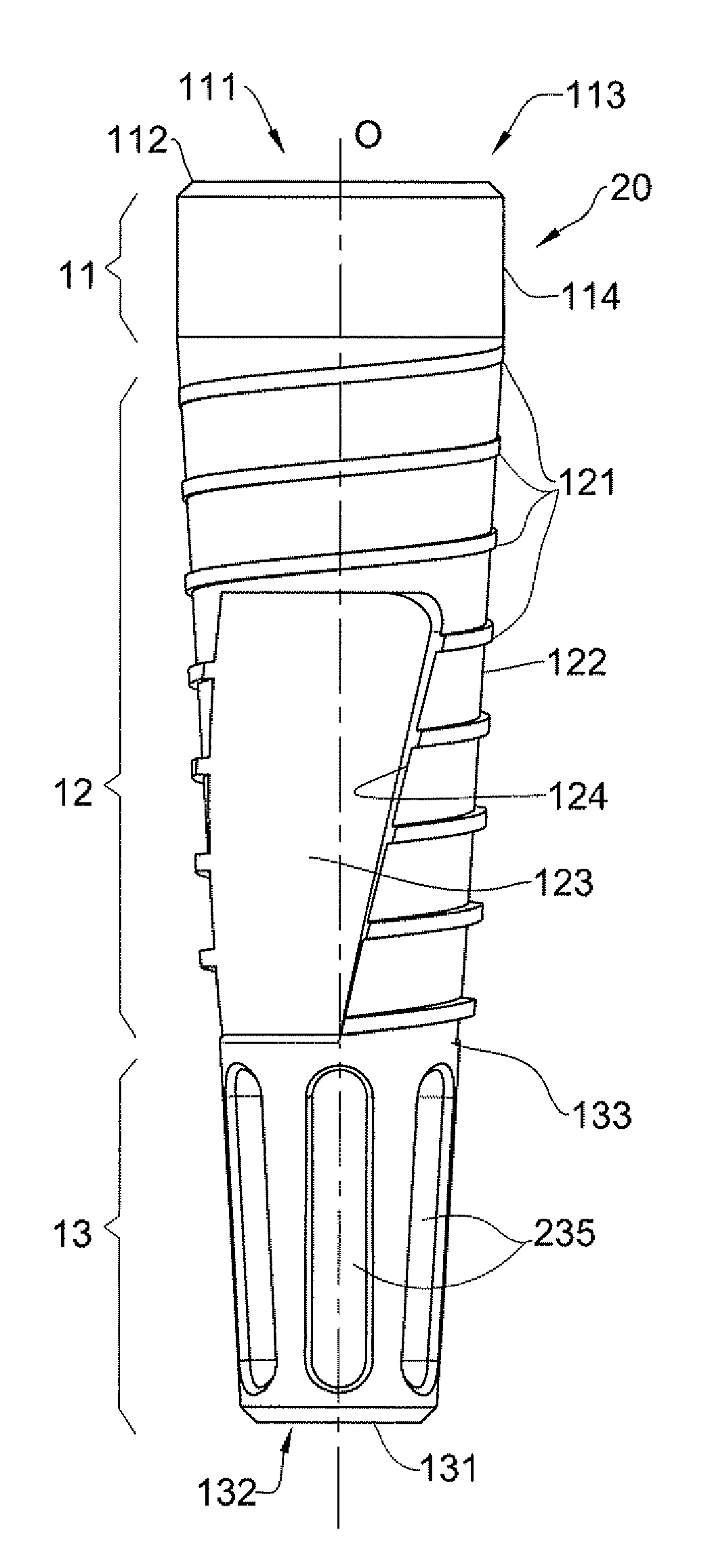
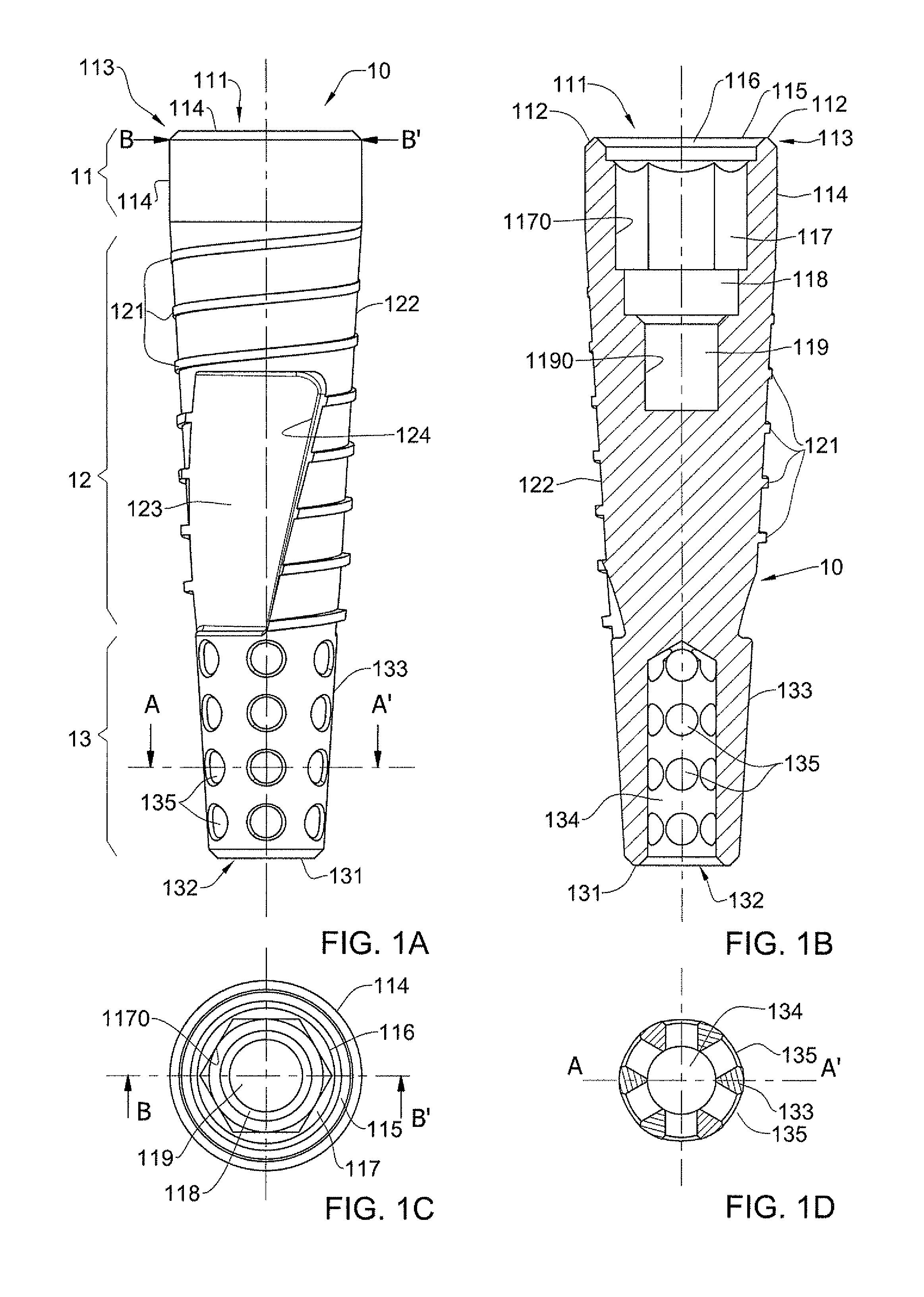
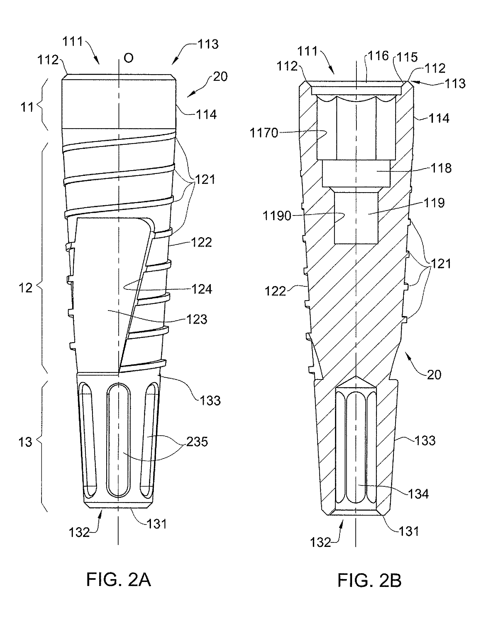
[0043]Referring to FIGS. 1A and 1B a schematic side elevational view and a longitudinal cross-sectional view of an endosseous dental implant 10 is illustrated, correspondingly, according to one embodiment of the present invention. It should be understood that the dental implant 10 is not bou...


PUM


Abstract

A dental implant for anchoring in a jawbone to support an abutment for mounting a dental prosthesis is described. The dental implant comprises a collar portion located at an open proximal distal end, a mid portion integrally connected to the collar portion and a base hollow portion integrally connected to a mid portion and located at an open distal end of said implant. The collar portion has an axial opening that extends into a blind hole proceeding from the proximal end into the interior of the implant and is configured to secure the abutment to the dental implant. The mid portion includes external helical treads turning around an external wall of the mid portion. The base hollow portion comprises a wall defining an internal storage volume for an osseous tissue of the jawbone. The base hollow portion comprises a plurality of openings arranged in the wall and entering the internal storage volume. The base hollow portion is unthreaded and tapered with contraction towards the distal end.

Description

FIELD OF THE INVENTION[0001]This invention relates to an endosseous implant for prosthesis embedded in the bone tissue of a living body, and in particular, to an endosseous dental implant.BACKGROUND OF THE INVENTION[0002]Endosseous dental implants are widely used in dental surgical procedures for restoration of one or more teeth in a patient's mouth using a prosthetic tooth that is secured to a dental abutment united with the dental implant anchored in the jawbone.[0003]Generally, the procedure for restoring a tooth includes several stages. In the beginning, an implant cavity of dimensions adapted to those of the implant is created by to drilling a hole of increasing diameter. Then, the dental implant is inserted into the hole, typically by screwing, although other techniques are known for introducing the implant in the jawbone. After the implant is initially installed in the bone, a temporary healing cap is secured over the exposed proximal end of the implant. The patient's gums ar...

Claims


Application Information

Patent Timeline
Patent Type & Authority Applications(United States)
IPC IPC(8): A61C8/00
CPCA61C8/0018A61C8/006A61C8/005A61C8/0039
Inventor ELYAV, ELKANA
Owner ELYAV ELKANA
Why Eureka
Try Eureka