Non-clogging non-pressure compensated drip emitter

a drip emitter and non-pressure compensation technology, applied in watering devices, horticulture, agriculture, etc., to eliminate the potential for clogging and eliminate the effect of clogging

Inactive Publication Date: 2010-04-22
MAMO SHAY
View PDF27 Cites 49 Cited by
  • Summary
  • Abstract
  • Description
  • Claims
  • Application Information

AI Technical Summary

Benefits of technology

[0009]One or more embodiments of the invention enable a non-clogging non-pressure compensated drip emitter. Embodiments include a hollow cylindrical emitter body having an inner cylindrical surface, an outer cylindrical surface, a first end and a second end. Embodiments may be constructed as a full cylinder or an arc of a full cylinder. Embodiments further include a filter or an inwardly offset filter that projects inwardly from the inner cylindrical surface of the hollow cylindrical emitter body. The filter does not clog when the emitter oriented rotationally downward in the field as the filter is not a potential well and hence sediment does not drop into it. In addition, the filter provides a snorkel effect that enables faster moving and cleaner water to enter the emitter via the filter, hence eliminating the potential to clog in a second manner. Thus the filter eliminates clogs in two ways, by avoiding sediment with a height offset and avoiding sediment by selecting faster moving water away from the pipe outer surface. An emitter may also utilize more than one filter in a redundant configuration to either supply both pools on each side of the emitter or alternatively to supply an associated pool in a one-to-one manner.
[0010]Embodiments further include a pool coupled with the outer cylindrical surface wherein the pool is configured to hold water filtered by the filter or inwardly offset filter when the hollow cylindrical emitter body is enclosed in a pipe. Embodiments further include a labyrinth coupled with the outer cylindrical surface wherein the labyrinth includes only turbulent transfer zones, at least after water enters the labyrinth, and wherein the labyrinth allows the water to flow from the filter or inwardly offset filter to the pool. Through the use of only turbulent transfer zones once the water enters the labyrinth, sediment is continuously forced through the labyrinth and has no location to settle and hence the labyrinth minimizes the potential to clog. In other words, laminar flow transfer zones are not utilized as these type of “straight” paths tend to clog over time with sediments. By utilizing a filter or an inwardly offset filter and a labyrinth that includes only turbulent transfer zones, the emitter minimizes the potential to clog in multiple ways.
[0013]In one or more embodiment of the invention, a symmetrical embodiment may be utilized that provides two pools and two labyrinths. This embodiment provides a robust redundant embodiment that continues to work even if one labyrinth were to clog, or if one hole into the pipe associated with a particular emitter were to be externally plugged, buried or blocked. Several embodiments of redundant configurations may be formed that include a two pool embodiment with one or more labyrinths, i.e., one labyrinth with a “T” or fork section, or two labyrinths, each flowing to a separate pool. Alternatively, the embodiment can be doubled to form more than one filter or inwardly offset filter, for example offset rotationally by 180 degrees, with separate labyrinth(s) and pool(s) coupled therewith for even more redundancy.

Problems solved by technology

In other words, laminar flow transfer zones are not utilized as these type of “straight” paths tend to clog over time with sediments.

Method used


Image

  • Non-clogging non-pressure compensated drip emitter
  • Non-clogging non-pressure compensated drip emitter
  • Non-clogging non-pressure compensated drip emitter

Examples


second embodiment

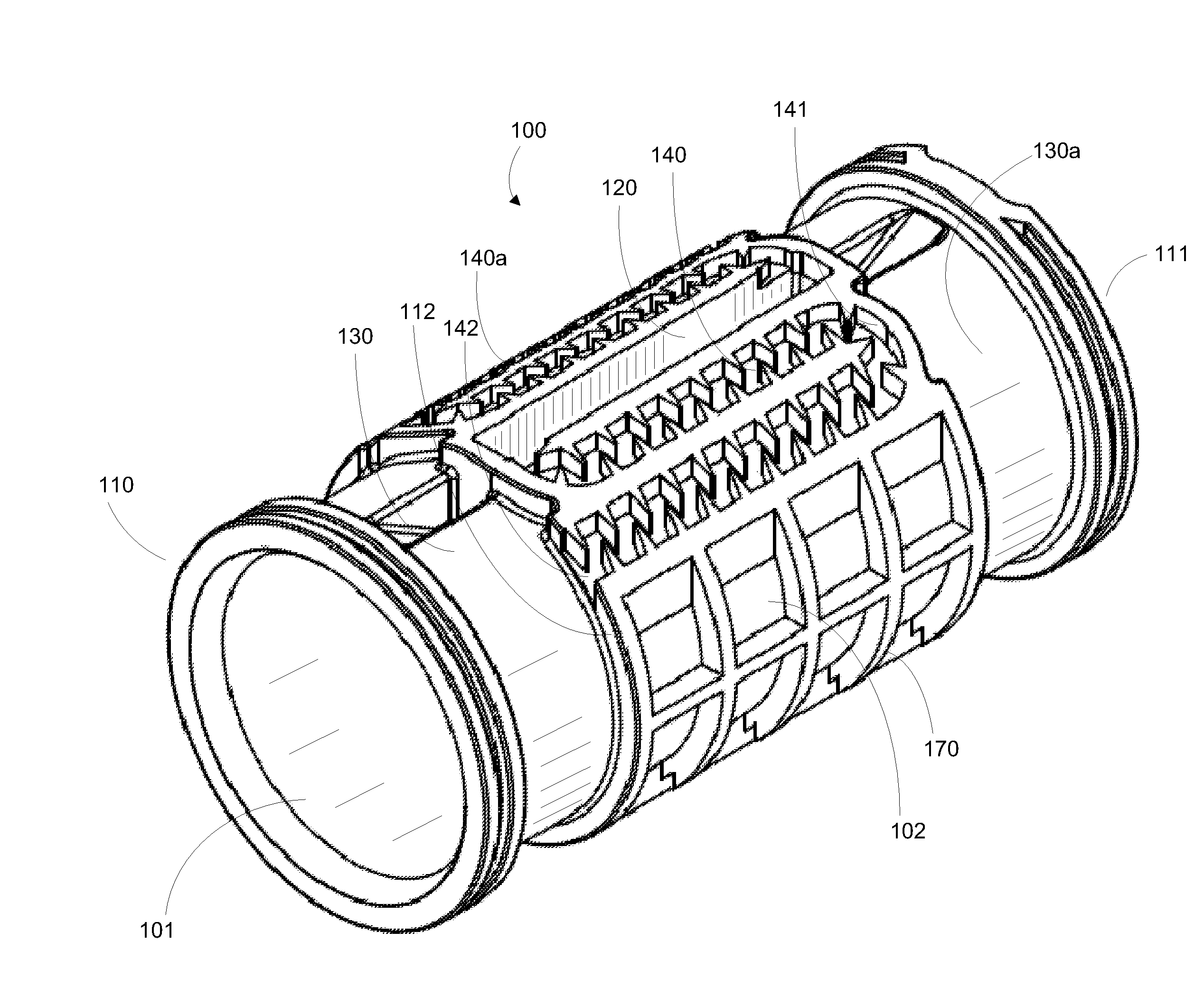
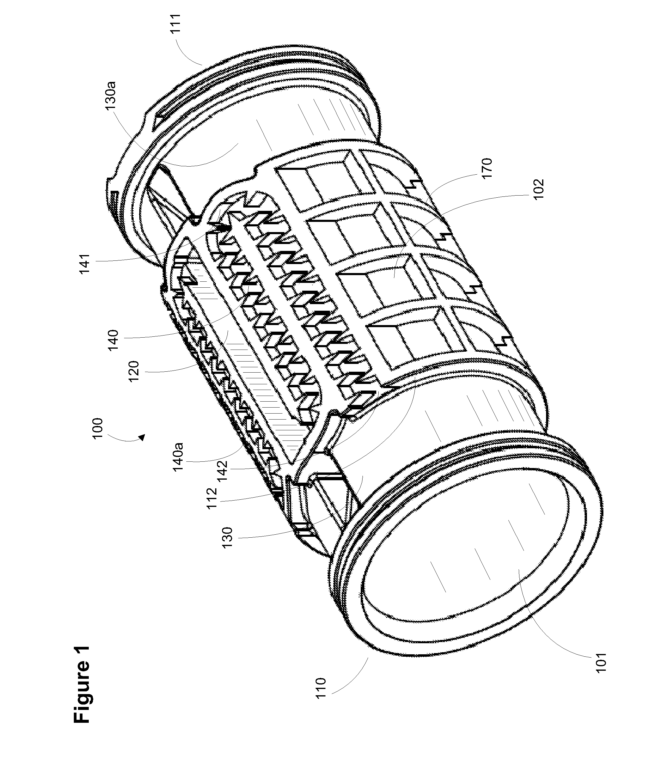
[0060]FIG. 8 is a perspective view of the non-clogging non-pressure compensated drip emitter. In this embodiment inwardly offset filter 120a is formed offset from the center looking down onto the emitter and exits labyrinth 140 into pool 130 and 130a.

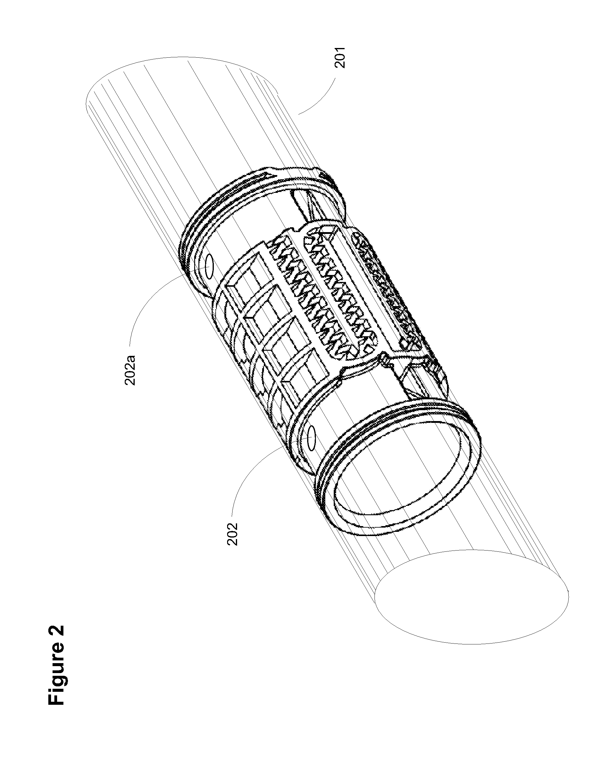
[0061]FIG. 9 is a perspective view of a second embodiment of the non-clogging non-pressure compensated drip emitter rotated 90 degrees about the lengthwise axis of the emitter and shown as situated inside pipe 201. In the figure, water flows through the labyrinth to fork 149 and exits the labyrinth at exit 142 and 142a and into the pools at each side of the emitter. Hence, this embodiment uses one labyrinth to supply two pools from one labyrinth entry point.

[0062]FIG. 10 is a top view of a second embodiment of the non-clogging non-pressure compensated drip emitter. In this figure, exits 142 and 142a are shown on each side of fork 149, which is a turbulent area so as to avoid clogging. There are two transfer zone locations 141 shown at ...

third embodiment

[0065]FIG. 13 is a perspective view of the non-clogging non-pressure compensated drip emitter. In this embodiment, redundant filters 120b are situated on the top (as shown) and on the bottom of the filter (see FIG. 14). Each filter 120b leads through a respective labyrinth 140, via labyrinth entry 301, through multiple transfer zone locations 141, to labyrinth exit 142 and into a respective pool (top filter flows into pool 130, while bottom filter flows into pool 130a). The remaining reference characters are as shown in the previous embodiments.

[0066]FIG. 14 is a perspective view of a third embodiment of the non-clogging non-pressure compensated drip emitter rotated 90 degrees about the lengthwise axis of the emitter. In this figure the redundant filter 120b is shown mirrored onto the right side of the figure (as opposed to the left side mirror location of filter 120b in FIG. 13). In addition, filter 120b filters water that flows into labyrinth entry 301, through labyrinth 140 and i...

fourth embodiment

[0074]FIG. 22 is a perspective view of the non-clogging non-pressure compensated drip emitter. In this embodiment filter 120c may be inwardly offset or flat with respect to the inner surface (underside as shown in the figure) of the emitter. This emitter may be placed inside a mount that is further located into a pipe or mounted with the top as shown in the figure directly against the inside of a pipe. Alternatively, more than one emitter may be mounted on a common mount and then placed inside a pipe to provide a radially redundant emitter. In this embodiment, filter 120c leads to mirrored labyrinths 140 via labyrinth entries 301 that allow water to flow into pools 130 and 130a respectively via labyrinth exits 142.

[0075]This embodiment is also a cylindrical embodiment as are the first three embodiments, however the arc of the cylinder formed by the top surface as shown is less than 360 degrees as shown in the first three embodiments of FIGS. 1-21, (the partial arc is also shown as t...


PUM

PropertyMeasurementUnit
depthaaaaaaaaaa
widthaaaaaaaaaa
diameteraaaaaaaaaa

Abstract

A non-clogging non-pressure compensated drip emitter that utilizes one or more filters or one or more inwardly offset filters that have an inlet that projects inwardly toward a centerline of the hollow cylindrical emitter body and a labyrinth having only turbulent transfer zones after water enters the labyrinth, wherein the labyrinth couples the filter(s) or inwardly offset filter(s) to the pool. Prevents clogging by eliminating dead transfer zones where sediment can accumulate where no turbulence exists. Also prevents clogging when the filter is positioned downward as the inwardly offset filter rises above any sediment when the emitter is positioned in the field in this downward orientation. Also prevents clogging flat filter configurations that have filters offset radially, i.e., redundant filters per emitter.

Description

BACKGROUND OF THE INVENTION[0001]1. Field of the Invention[0002]Embodiments of the invention described herein pertain to the field of irrigation apparatus. More particularly, but not by way of limitation, one or more embodiments of the invention enable a non-clogging non-pressure compensated drip emitter.[0003]2. Description of the Related Art[0004]There are multiple types of irrigation drippers. Simple drippers exist that are inserted serially along pipe, either by forcing a hole into the pipe and placing the dripper on the outside of the pipe, or by cutting the pipe and inserting the dripper in line with the pipe. These systems require great amounts of labor when providing a watering system for a large agricultural area for example.[0005]Other types of drippers include drip emitters that are inserted into pipe, generally when the pipe is extruded. This type of dripper system enables rapid deployment of great lengths of pipe, i.e., dripper line, wherein the drippers may be ordered ...

Claims


Application Information

Patent Timeline
Patent Type & Authority Applications(United States)
IPC IPC(8): B05B15/00
CPCA01G25/023B29C45/1671B29C45/14598
Inventor MAMO, SHAY
Owner MAMO SHAY
Why Eureka
Try Eureka