
Rupture-resistant compliant radiopaque catheter balloon and methods for use of same in an intravascular surgical procedure

a radiopaque catheter and catheter shaft technology, applied in the field of medical devices, can solve the problems of warping of the catheter shaft, limiting the usefulness or marketability of the catheter, harming the patient, etc., and achieve the effect of marked increase in the deflation time before the removal of the balloon from the body

Inactive Publication Date: 2014-11-13
VECTOR CORP
View PDF3 Cites 1 Cited by
  • Summary
  • Abstract
  • Description
  • Claims
  • Application Information

AI Technical Summary

Benefits of technology

[0013]The present invention provides a compliant catheter balloon having improved wall integrity and radiopaque properties to facilitate accurate and safe intraluminal placement and inflation of the balloon within body cavities. In particular, the invention provides a fully radiopaque balloon with co-extensive reinforcement by non-compliant fibers, wherein the radiopaque balloon material is visualizable in an unobstructed manner within an intraluminal space. In preferred embodiments, the radiopaque material is disposed on the balloon in a fashion that aids in its folding. In especially preferred embodiments, the radiopaque coating is disposed on the balloon in a fashion which negates the need for use of any contrast media for visualization of the balloon during the procedure. In such embodiments, saline may be used as the sole inflation medium.
[0014]Accordingly, in one aspect, a radiopaque balloon for use with an intraluminal catheter is provided. The balloon includes an inner inflation layer, including a compliant polymeric cylinder defining a lumen for retention of inflation fluid. A fiber layer, is disposed on the inflation layer. The fiber layer includes at least two layers of inelastic, non-braided fibers disposed around the length of the inner wall by adhesive means, with the fibers of each layer separated by the adhesive means. Use of non-braided fibers improves inflation control by eliminating the potential for inter-fiber expansion.
[0019]In methods for use of the balloon of the invention to perform an intravascular surgical procedure, the balloon is mounted on an appropriate catheter and advanced through a body vessel of a subject to a treatment site. Where the balloon is coated along substantially its entire length with a radiopaque coating, and especially when substantially the entire surface of the balloon is covering by the coating, inflation is achieved using only saline as an inflation medium. Use of contrast media for visualization of the balloon during the procedure is avoided, and deflation times prior to removal of the balloon from the body are markedly increased; e.g., by at or around 50% compared to the time required for deflation of a balloon containing contrast medium.

Problems solved by technology

Accurate placement of the balloon with respect to the portion of the body vessel being treated is critical, as misplacement can reduce therapeutic efficacy and potentially cause harm to the patient.
However, each of these prior art approaches poses difficulty in manufacturing and use of the balloon catheter systems that limit their usefulness or marketability.
However, coating the catheter with radiopaque bands stiffens it at the application site, and often exposes the catheter material (usually a polymer) to melt temperatures that can cause warp of the catheter shaft.
The narrower the overall catheter system, the more flexible it is and the more susceptible it will be to use in a wider variety of vessel sizes.
Coating the interior luminal surface of a balloon allows use of thinner balloon materials, but requires coating and finishing of the balloon prior to catheter mounting, limiting manufacturing options for the system.
Further, if the balloon is not fully radiolucent (either because the balloon polymer isn't radiolucent, or because it is coated or wrapped with non-radiolucent reinforcements), visualization of the radiopaque material within the balloon can be impaired.
While one might be able to use such an intraluminally coated balloon without reinforcement, balloon resistance to breakage on overinflation is a critical concern, in that such breakage can have severe adverse effects on the patient.
Yet failing to provide reinforcements that are co-extensive with substantially the entire surface of the balloon provides the latter with inherent points of weakness, diminishing safety.

Method used


Image

  • Rupture-resistant compliant radiopaque catheter balloon and methods for use of same in an intravascular surgical procedure
  • Rupture-resistant compliant radiopaque catheter balloon and methods for use of same in an intravascular surgical procedure
  • Rupture-resistant compliant radiopaque catheter balloon and methods for use of same in an intravascular surgical procedure

Examples


example 1

Fabrication of Compliant Radiopaque Balloon Having a Braided Fiber Layer

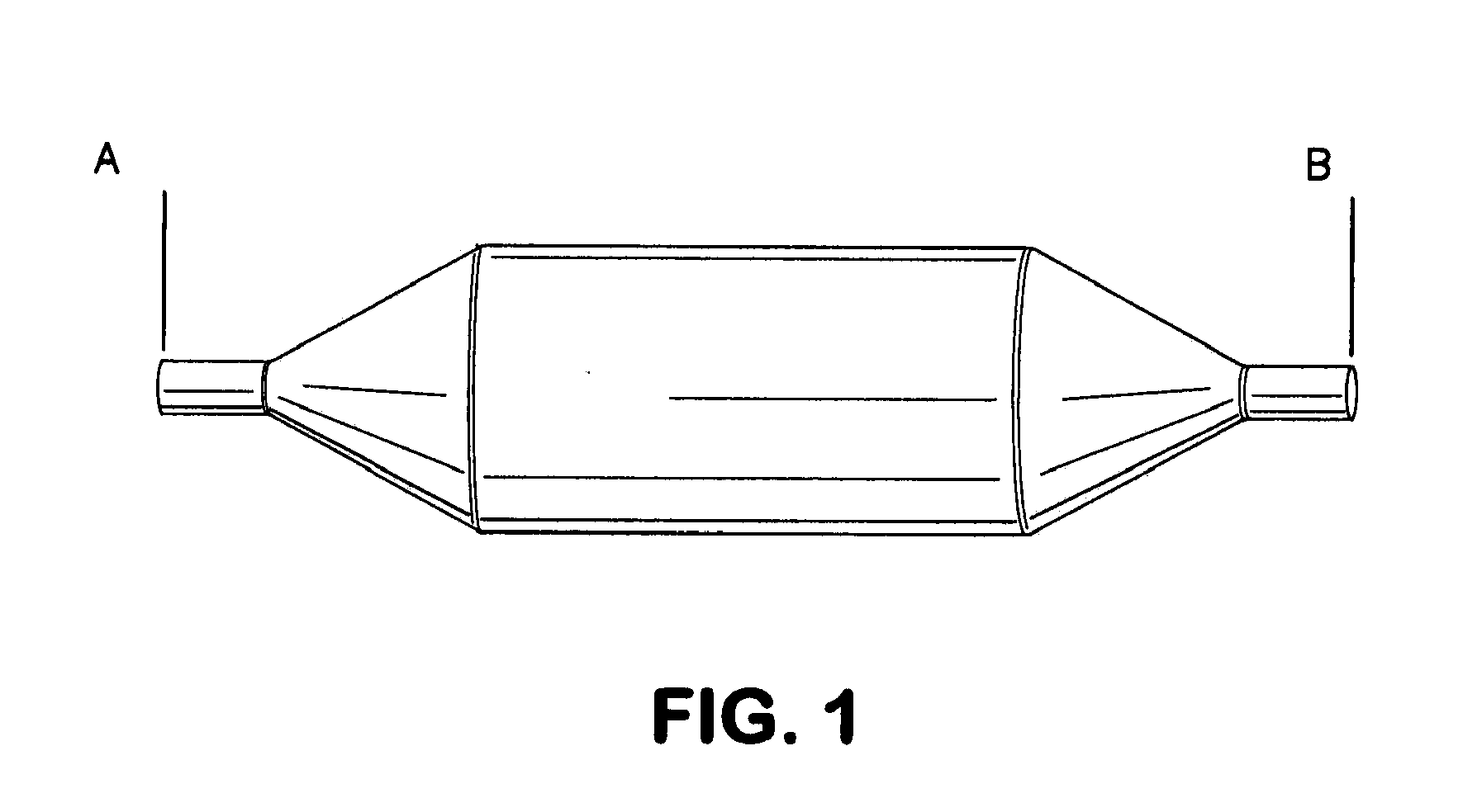
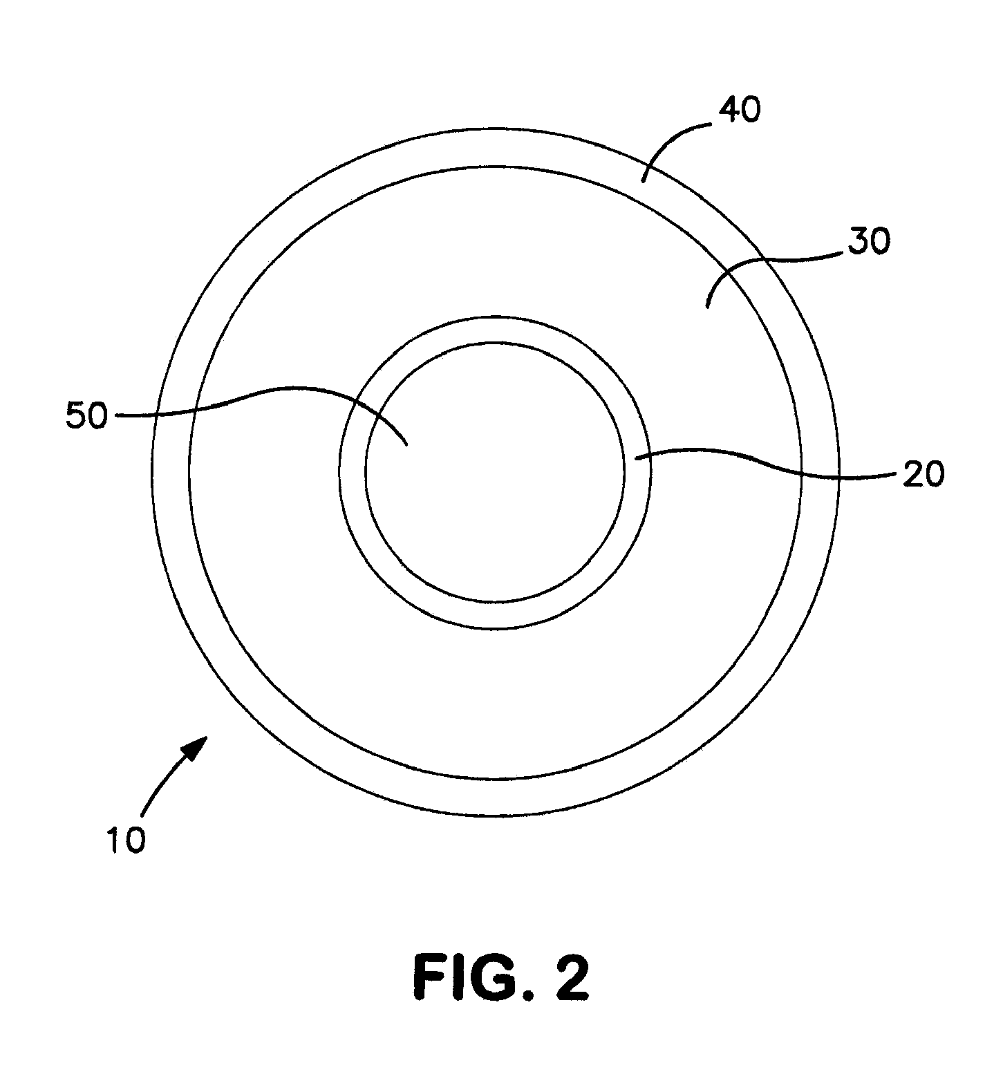
[0069]Balloons were constructed having the general cross-sectional design configuration depicted in FIG. 2. Shown in an inflated state, the balloons generally included an inflation layer 20, a fiber layer 30, and a coating layer 40. The inflation layer 20 defines a lumen 50 for retention of inflation fluid used to increase the internal pressure of the lumen 50 to inflate the balloon 10. With reference to FIGS. 2 and 4, the balloons included the following components: inner balloon or inflation layer 20, fiber layer 30, coating layer 40, and deposited directly on the outer surface of the inflation layer 200 is radiopaque layer 210. Materials used for each component are shown in Table 1 as follows.

TABLE 1Balloon Component Materials ListBalloon ComponentMaterial Description / SpecificationInflation LayerVestamid ® Nylon(Inner Balloon) (20)RadiopaqueEpoxy based ink with >95% tungstenCoating (210)Fiber Layer (30)Ultra H...

example 2

Fabrication of Compliant Radiopaque Balloon Having a Fiber Layer Including Braided and Non-Braided Fiber

[0073]Balloons were constructed in a process similar to that discussed in Example 1 with variations to the fiber layer 30. For example, a balloon was constructed including in which the fiber layer 30 includes both a first non-braided layer and a second braided fiber layer. The balloon materials are those shown in Table 1.

[0074]To construct the balloons, inflation layer 20 was first formed from compliant nylon material using a blow molding process. Next, radiopaque coating 210 was optionally applied to the outer surface of the inflation layer 200 via printing in a longitudinally striped pattern along the ‘working’ length of the balloon (e.g., the region between the conical regions of the balloon) or to substantially the entire outer surface of the inflation layer 200. Fiber layer 30 was next formed by applying a thin coat of adhesive to the outer surface of the inflation layer 200 ...

example 3

Inflation and Deflation Rates of Balloons Utilizing Various Mixtures of Inflation Fluid

[0078]Inflation and deflation rates were tested for a balloon utilizing various ratios of saline to contrast media as inflation fluid. To perform the experiment, a 6 mm diameter by 10 cm balloon (Bard Dorado®) was tested. It is important to note that unlike the balloon of the present invention, the balloon used to perform the experiment requires the inflation fluid to include 50% or greater of contrast media in a surgical setting to be functional for the surgical procedure. Three trails were performed using saline alone and a 50:50 saline to contrast media mixture. The results are shown in Table 2 below.

TABLE 2Balloon Catheter Inflation and Deflation RatesBalloonCatheterSaline50 / 50 Contrast SalineTrialsInflate (Sec.)Deflate (Sec.)Inflate (Sec.)Deflate (Sec.)1 18*8131721591219314101220Avg.  14.509.0012.3318.67

[0079]As shown in Table 2, the deflation times observed show that increasing the viscosity...


PUM


Abstract

The present invention provides a compliant balloon for use with a catheter having an inner compliant inner layer defining a cylindrical lumen encased by a fiber layer including non-braided inelastic fibers imparting integrity to the balloon wall. The balloon further includes radiopaque material which may be disposed over substantially the entire length of the balloon as a coating or by incorporation within the fiber layer or an outer coating layer. The balloon is expandable from a folded deflated state to an inflated state by increasing pressure within the balloon and can be used with saline as the sole inflation medium to allow rapid deflation as compared to use of a balloon with a contrast medium.

Description

CROSS REFERENCE TO RELATED APPLICATION(S)[0001]This application is a continuation application of U.S. application Ser. No. 12 / 610,102, filed Oct. 30, 2009, now pending; which claims the benefit of priority under 35 U.S.C. §119(e) of U.S. Ser. No. 61 / 109,840, filed Oct. 30, 2008, the entire content of which is incorporated herein by reference.BACKGROUND OF THE INVENTION[0002]1. Field of the Invention[0003]The invention relates generally to medical devices and more specifically to radiopaque catheter balloons for use with balloon catheters.[0004]2. Background Information[0005]Balloon catheters are used in various medical procedures to treat lesions in intraluminal body cavities, predominantly within vascular vessels and arteries, as well as the urethra. Accurate placement of the balloon with respect to the portion of the body vessel being treated is critical, as misplacement can reduce therapeutic efficacy and potentially cause harm to the patient.[0006]One widely used procedure that ...

Claims


Application Information

Patent Timeline
Patent Type & Authority Applications(United States)
IPC IPC(8): A61M25/10
CPCA61M25/104A61M2025/1075A61M2025/1079
Inventor ALLEX, STEVEN J.GEER, DONALDWILLIAMS, BRETT ALLYNHATCHER, BRADY JONTIESO, TRISTAN LYNN
Owner VECTOR CORP
Learn More