Method and system for precise-clock synchronization, and device for precise-clock frequency/time synchronization

a clock synchronization and frequency synchronization technology, applied in the field of communication technology, can solve the problems of inability to perform correct calculation according to the obtained time stamp, too much link bandwidth resources are occupied in the foresaid process, and the clock synchronization occupies too much link bandwidth resources, so as to achieve the effect of greatly reducing the occupied link bandwidth resources

Inactive Publication Date: 2010-04-22
HUAWEI TECH CO LTD
View PDF20 Cites 69 Cited by
  • Summary
  • Abstract
  • Description
  • Claims
  • Application Information

AI Technical Summary

Benefits of technology

[0006]Embodiments of the present invention provide a precise-clock synchronization method and system and a precise-clock frequency / time synchronization device, so that the frequency synchronization and time synchronization of the clocks do not interfere with each other, and the occupied link bandwidth resources are greatly reduced.
[0024]As can be seen from the technical solution above, in the embodiments of the present invention, the precise-clock synchronization method and system and the precise-clock frequency / time synchronization device may accomplish frequency synchronization and time synchronization of the master clock and the slave clock independently by using time stamps provided by two different time stamp engines, so that the frequency synchronization and time synchronization of the clocks do not interfere with each other, thus greatly reducing the occupied link bandwidth resources.

Problems solved by technology

Too much link bandwidth resources are occupied in the foresaid process.
Especially, when the network transmission conditions are deteriorated and the frequency of transmitting packets needs to be increased for frequency synchronization, such a disadvantage that the clock synchronization occupies too much link bandwidth resources becomes more apparent.
Therefore, correct calculation is not able to be performed according to the obtained time stamps, and the frequency synchronization / time synchronization is thus influenced.

Method used


Image

  • Method and system for precise-clock synchronization, and device for precise-clock frequency/time synchronization
  • Method and system for precise-clock synchronization, and device for precise-clock frequency/time synchronization
  • Method and system for precise-clock synchronization, and device for precise-clock frequency/time synchronization

Examples


first embodiment

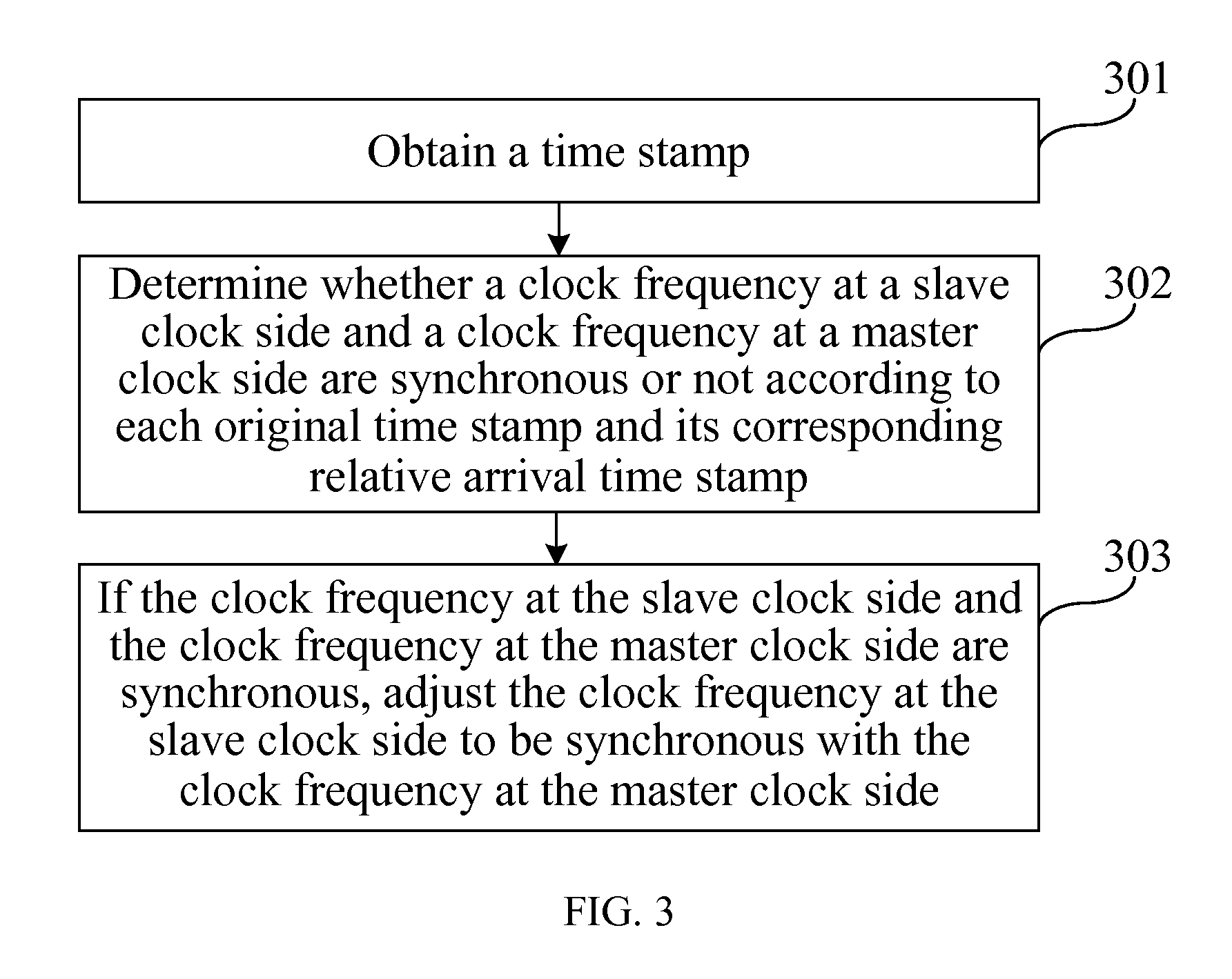
[0056]FIG. 3 is a schematic flow chart of a precise-clock synchronization method according to the present invention. Referring to FIG. 3, the precise-clock synchronization method includes the following steps.

[0057]In step 301, a time stamp is obtained. The time stamp includes at least an original time stamp about the time when a master clock side transmits each Sync packet and a relative arrival time stamp about the time when each Sync packet is received.

[0058]The original time stamp is a time of transmitting the Sync packet stamped at the master clock side, that is, the time of the master clock. The relative time stamp is a local time when the slave clock side receives the Sync packet, that is, the time of the slave clock.

[0059]In step 302, it is judged whether a clock frequency at the slave clock side is synchronous with a clock frequency at the master clock side or not according to each original time stamp and its corresponding relative arrival time stamp.

[0060]In step 302, sever...

second embodiment

[0063]FIG. 4 is a schematic flow chart of a precise-clock synchronization method according to the present invention. Referring to FIG. 4, the precise-clock synchronization method includes the following steps.

[0064]In step 401, a Sync packet transmitted by a master clock side is received.

[0065]In step 402, a time stamp is obtained from the Sync packet. The time stamp includes an original time stamp about the time when the master clock side transmits each Sync packet and a relative arrival time stamp about the time when each Sync packet is received.

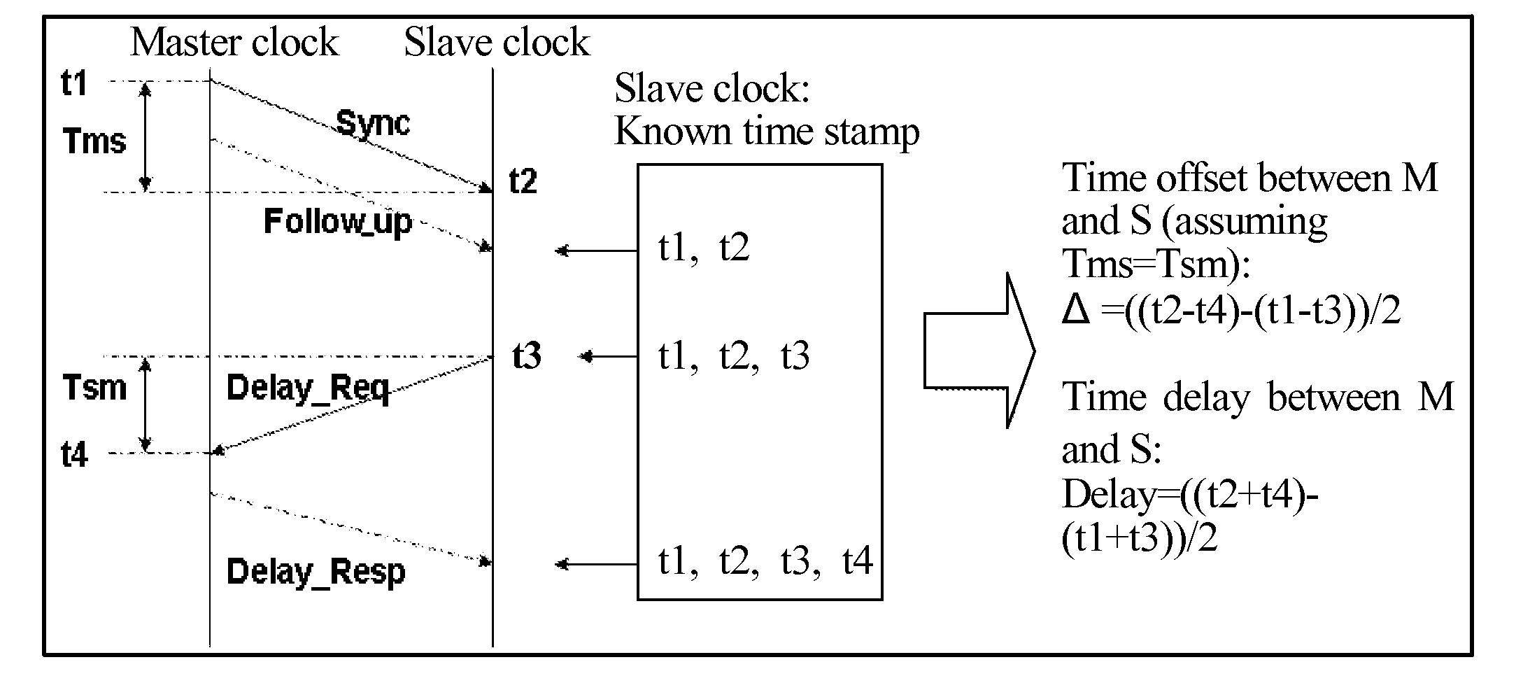
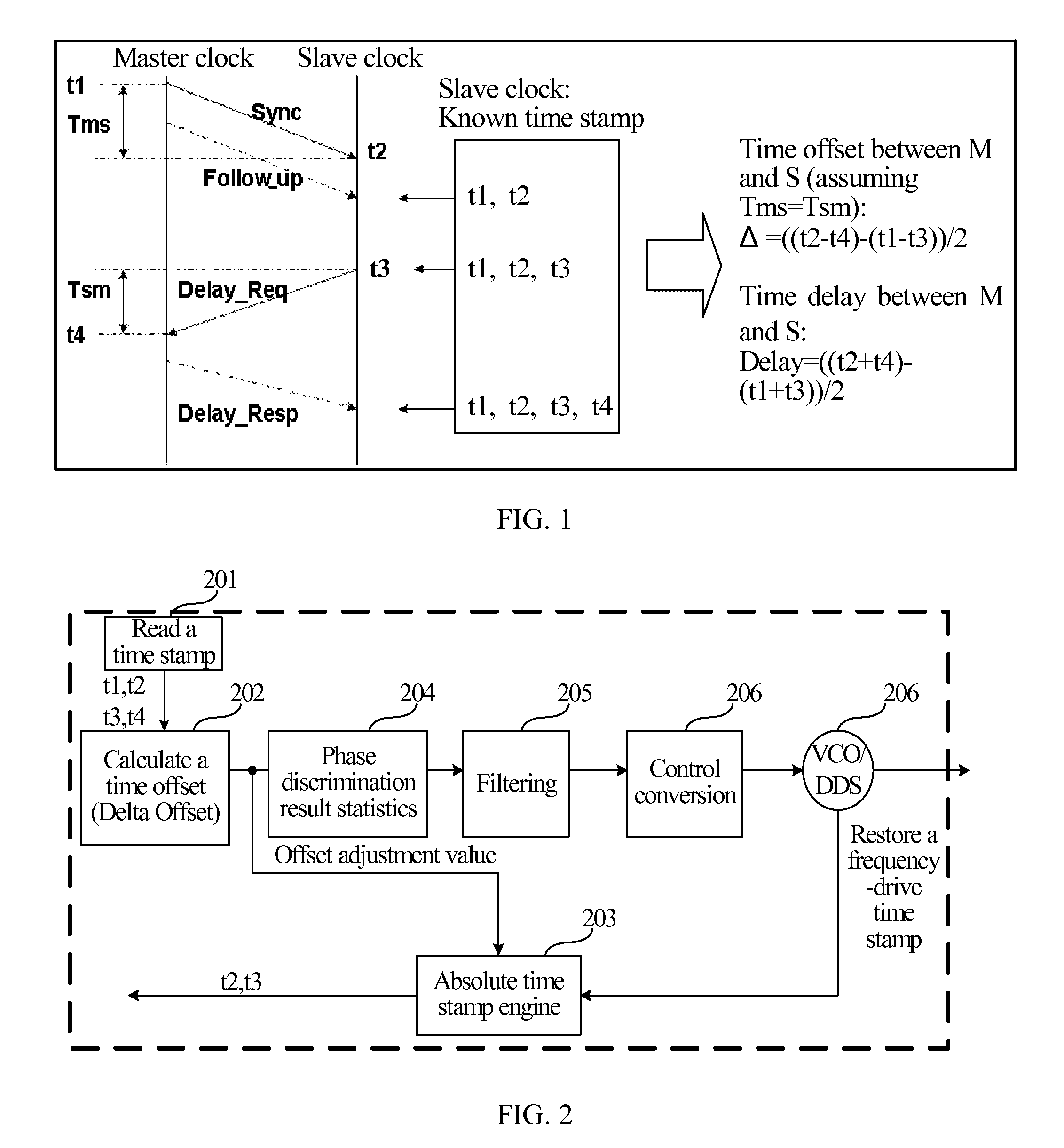
[0066]As shown in FIG. 1, the original time stamp of the Sync packet is a time t1 when the master clock side transmits the Sync packet. The relative arrival time stamp of the Sync packet is transmitted locally, that is, transmitted by the relative time stamp engine at the slave clock side. The relative time stamp engine does not need time setting and is only used for frequency synchronization. Therefore, the relative arrival time stamp obta...

fourth embodiment

[0101]FIG. 7 is a schematic flow chart of a precise-clock synchronization method according to the present invention. Referring to FIG. 7, the precise-clock synchronization method includes the following steps.

[0102]In step 701, a time stamp including an original time stamp, an absolute arrival time stamp, and a Delay_Resp time stamp of a Sync packet transmitted by a master clock side, as well as a Delay_Req time stamp transmitted by the slave clock side are obtained.

[0103]The master clock side transmits the Sync packet. The slave clock side transmits a Delay_Req after receiving the transmitted Sync packet for a set period of time. The master clock side transmits a Delay_Resp after receiving the Delay_Req. The slave clock side receives the Delay_Resp. Time stamps, i.e. the time stamps obtained in step 701 are stamped in the packets.

[0104]In step 702, a time offset is calculated according to the obtained original time stamp, absolute arrival time stamp, Delay_Req time stamp, and Delay_...


PUM


Abstract

A precise-clock synchronization method and system and a precise-clock frequency / time synchronization device are provided. In the embodiments of the present invention, two time stamp engines are provided at a slave clock side. A relative time stamp engine provides a relative arrival time stamp. An absolute time stamp engine provides an absolute arrival time stamp. The frequency / time synchronization is calculated by using different time stamps obtained from different time stamp engines, so the frequency synchronization and time synchronization of master clock and the slave clock may be separately accomplished, and one synchronization function may be enabled or disabled. Therefore, the frequency synchronization and time synchronization of the master clock and the slave clock do not interfere with each other, thus greatly reducing the occupied link bandwidth resources.

Description

CROSS-REFERENCE TO RELATED APPLICATION[0001]This application claims priority to Chinese Patent Application No. 200810224615.7, filed Oct. 21, 2008, the content of which is hereby incorporated by reference in its entirety.FIELD OF THE TECHNOLOGY[0002]The present invention relates to the field of communication technology, and more particularly, to a method and system for precise-clock synchronization and a device for precise-clock frequency / time synchronization.BACKGROUND OF THE INVENTION[0003]IP-based communication networks have not reduced demands for clock synchronization. On the contrary, for demands of cost, safety, and services, the IP clock synchronization becomes more and more important. Among the various existing IP clock technologies, such as circuit emulation services over packet switched (CESoP), timing over packet (ToP), network time protocol (NTP), the ToP technology is a relatively new technology. For the IP clock technology, the IEEE also introduced an IEEE 1588 precis...

Claims


Application Information

Patent Timeline
Patent Type & Authority Applications(United States)
IPC IPC(8): H04J3/06
CPCH03L7/0807H04L43/106H04L43/0858H04J3/0667
Inventor SUN, WENHUAWANG, XIAOBOWANG, JIHUIXU, WENGUANGYANG, SHENGBINGDENG, YOUHAOLI, BINGBO
Owner HUAWEI TECH CO LTD
Why Eureka
Try Eureka