
Barrier assembly for use with needleless connector

a technology of barrier assembly and needleless connector, which is applied in the direction of valve operating means/release devices, catheters, couplings, etc., can solve the problems of increasing costs, prolonging hospital stays, and expensive approaches in terms of material and time required

Inactive Publication Date: 2010-04-22
BAXTER INT INC +1
View PDF13 Cites 34 Cited by
  • Summary
  • Abstract
  • Description
  • Claims
  • Application Information

AI Technical Summary

Benefits of technology

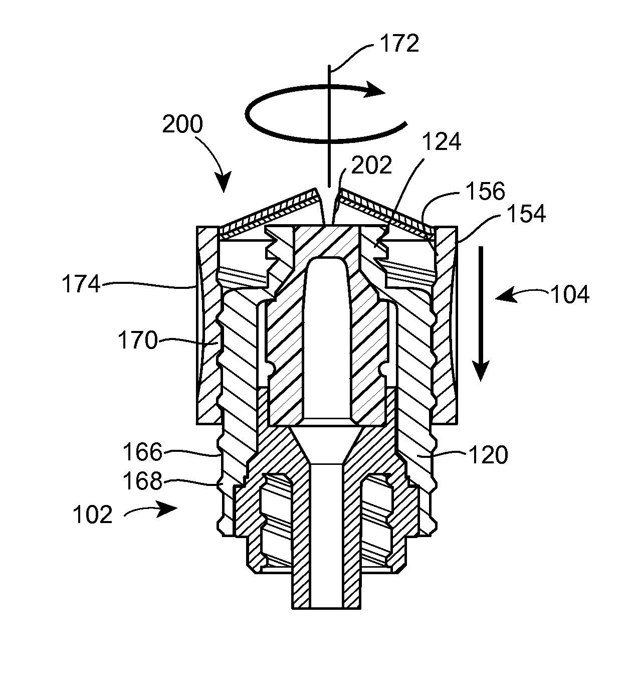
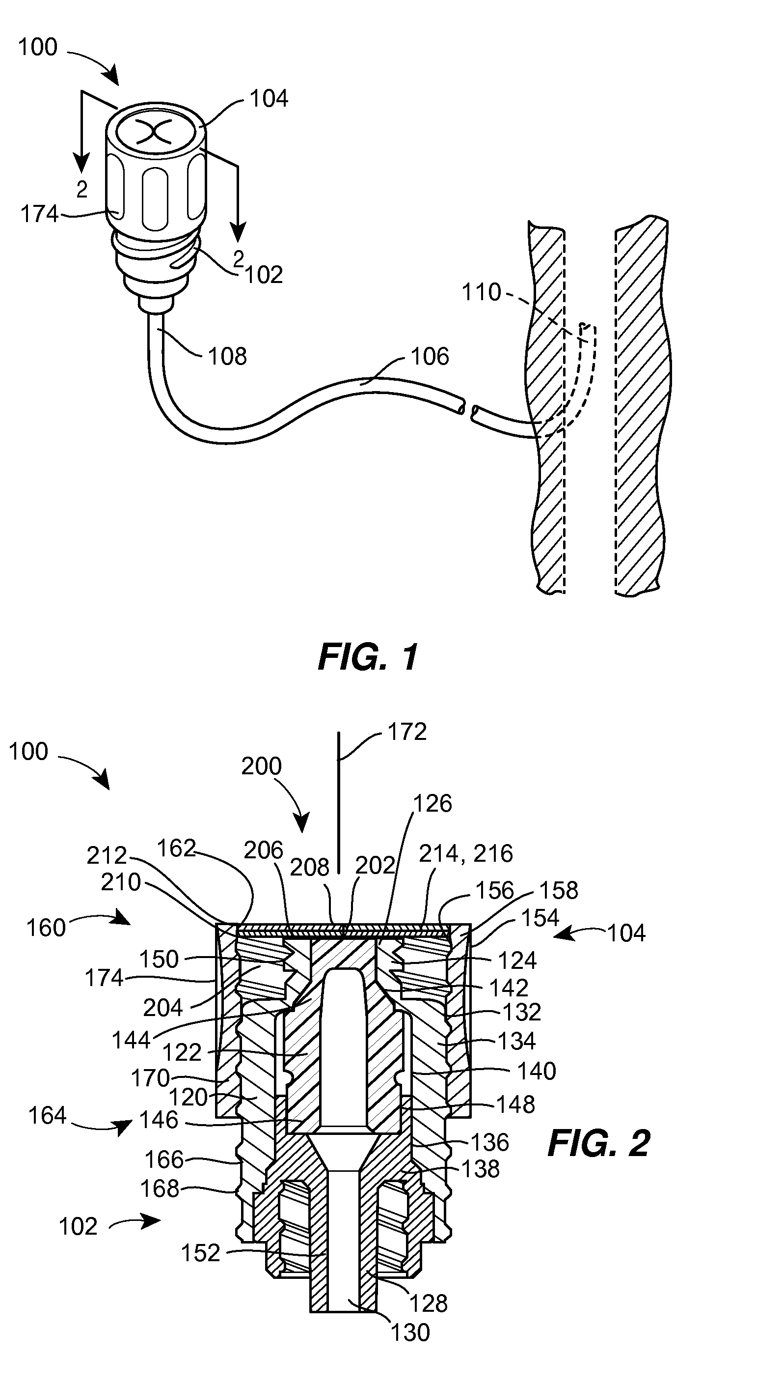
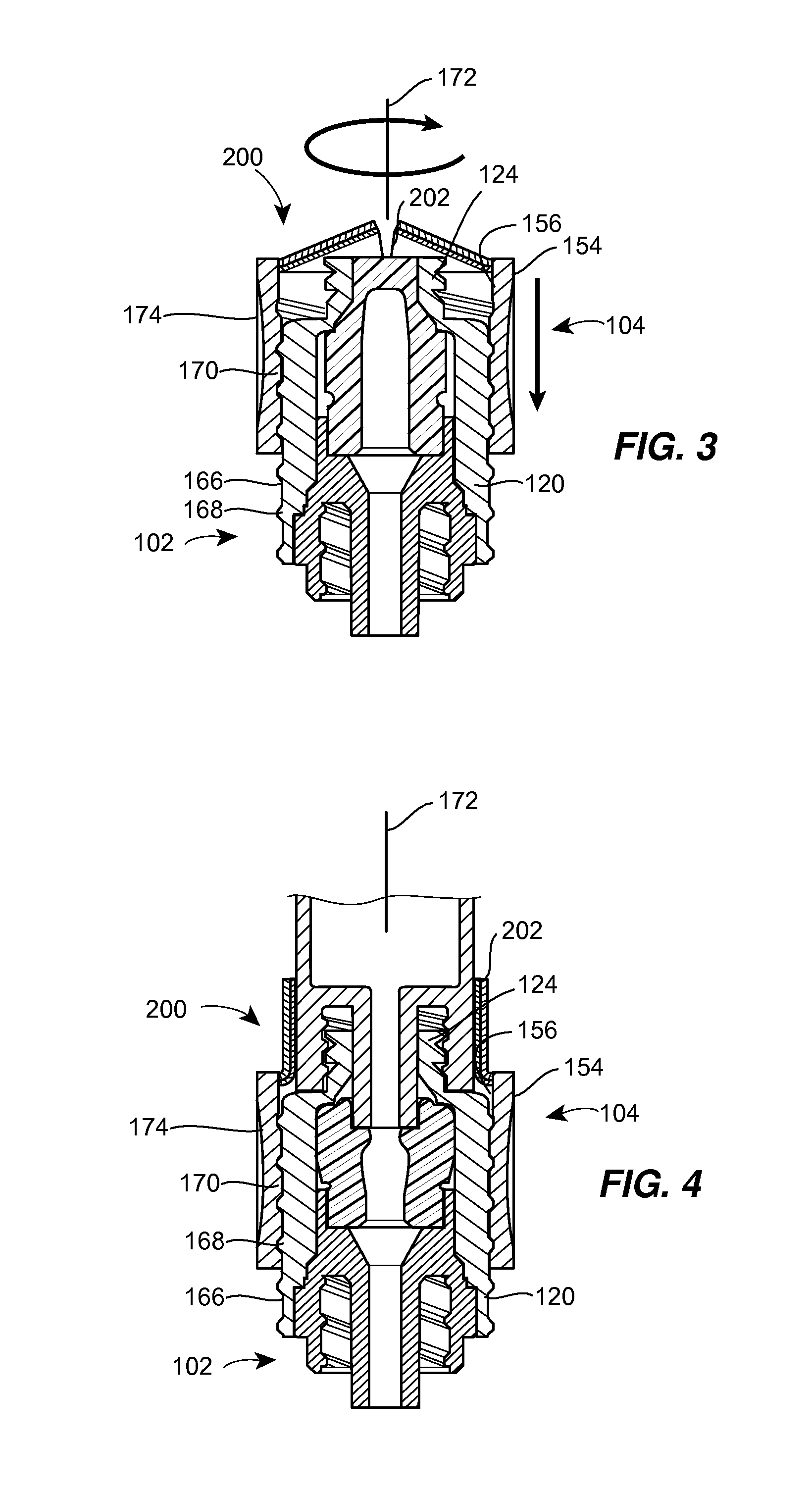
[0009]In one aspect, a needleless valve assembly includes a needleless connector having a housing with an inlet end with an inlet opening and an outlet end with an outlet opening, and a valve disposed in the housing to control passage between the inlet opening and the outlet opening. The assembly also includes a collar having an exterior surface and an interior surface, and a first end with a collar opening communicating between the interior surface and the exterio

Problems solved by technology

Bloodstream infections may not only prolong hospital stays, increasing costs, but may cause serious complications for the patient, potentially resulting in death.
This approach is costly in terms of material and time required, and actually may present additional opportunities for contamination to occur because the caps can become inadvertently contaminated through routine handling, where organisms are transferred from the skin or other contaminated surfaces.
However, proper technique is not always possible, because of the need to administer emergency care on a time critical basis, for example, and because even perfect technique may not reach crevices or interstitial spaces that are difficult or impossible to disinfect.
However, because the cap is detached from the valve, it remains possible for the cap not to be properly replaced after use of the valve.
Further, removal of the cap and its placement on a surface or its dangling from the connector can expose the cap to contamination, such as in the form of colonizing pathogens or general particulate.

Method used


Image

  • Barrier assembly for use with needleless connector
  • Barrier assembly for use with needleless connector
  • Barrier assembly for use with needleless connector

Examples


Embodiment Construction

[0022]Although the following text sets forth a detailed description of different embodiments of the invention, it should be understood that the legal scope of the invention is defined by the words of the claims set forth at the end of this patent. The detailed description is to be construed as exemplary only and does not describe every possible embodiment of the invention since describing every possible embodiment would be impractical, if not impossible. Numerous alternative embodiments could be implemented, using either current technology or technology developed after the filing date of this patent, which would still fall within the scope of the claims defining the invention.

[0023]It should also be understood that, unless a term is expressly defined in this patent using the sentence “As used herein, the term ‘______’ is hereby defined to mean . . . ” or a similar sentence, there is no intent to limit the meaning of that term, either expressly or by implication, beyond its plain or ...


PUM


Abstract

A needleless valve assembly includes a needleless connector having a housing with an inlet end with an inlet opening and an outlet end with an outlet opening, and a valve disposed in the housing to control passage between the openings. The assembly also includes a collar having an exterior surface and an interior surface, and a first end with a collar opening communicating between the interior surface and the exterior surface and a second end moveably attached to the housing. Further, the assembly includes a barrier disposed across the collar opening with a slit therethrough and including an anti-microbial material. The collar is moveable relative to the housing so that the inlet end of the housing depends past the exterior surface of the collar through the slit in the barrier. A kit may include the assembly and a catheter having a first end attached to the outlet opening.

Description

BACKGROUND[0001]This patent is directed to a barrier assembly for use with a needleless connector, and, in particular, to a barrier assembly for use with a needleless connector wherein the barrier assembly includes a moveable collar and an anti-microbial material.[0002]Intravenous (“I.V.”) therapy involves the delivery of fluids to a patient through a vein. For example, a catheter is placed into the vein of the patient, and then fluids are administered to the patient through the catheter. Typically, the catheter is connected to an administration set in communication with a container, such as a flexible container or bag, from which fluids are infused into the patient.[0003]One way in which the catheter has been attached to the administration set is through the use of needleless connectors. Needleless connectors reduce the risk of accidental sharps injuries to the patient and the healthcare worker. One common type of needleless connector is the Luer-activated valve or device. Another ...

Claims


Application Information

Patent Timeline
IPC IPC(8): A61M5/00
CPCA61M2039/261A61M39/165
Inventor CAWTHON, DUSTIN C.LAL, BIRENDRA K.
Owner BAXTER INT INC
Learn More