Portable solar-heating system having an inflatable solar collector

a solar collector and solar energy technology, applied in solar heat systems, sustainable buildings, light and heating apparatus, etc., can solve the problems of unattractive consumer, unreliable solar energy storage, and unreliable storage, and achieve the effect of convenient deployment and removal, low cost, and convenient us

Active Publication Date: 2010-04-29
PELLEGRINO STEPHEN T
View PDF32 Cites 13 Cited by
  • Summary
  • Abstract
  • Description
  • Claims
  • Application Information

AI Technical Summary

Benefits of technology

[0009]Disclosed herein are various embodiments of a solar-heating system having an inflatable solar collector connected to a housing that can be installed, e.g., in a sash window of a house. The housing has an air blower that draws air from the interior of the house and directs it into the inflatable solar collector, which is positioned outside the window. The collector has a flexible permeable membrane that serves as a transpired absorber of solar radiation. The air flowing through the collector is heated when it percolates through the membrane exposed to solar light. The heated air is returned back to the interior of the house, thereby providing space heating. In certain embodiments, in addition to serving as a transpired absorber, the membrane can also serve as an air filter that removes particles, odor-causing pollutants, and / or allergens from the drawn air. Advantageously, inflatable solar collectors of the invention can be manufactured using inexpensive, durable, and readily available materials. The collectors are inherently resilient to impact and shock, relatively easy to deploy and remove as needed, easy to adjust to the surrounding terrain and secure at a desired tilt angle, and easy to clean.

Problems solved by technology

For example, a relatively expensive solar-heating system has a relatively long pay-back period, which makes it unattractive to the consumer.
A solar-heating system that is permanent or difficult to deploy might similarly be unattractive because the consumer might prefer to have it deployed only when needed, e.g., during the winter months, and have it removed when not needed, e.g., during the periods of hot weather.

Method used


Image

  • Portable solar-heating system having an inflatable solar collector
  • Portable solar-heating system having an inflatable solar collector
  • Portable solar-heating system having an inflatable solar collector

Examples


Embodiment Construction

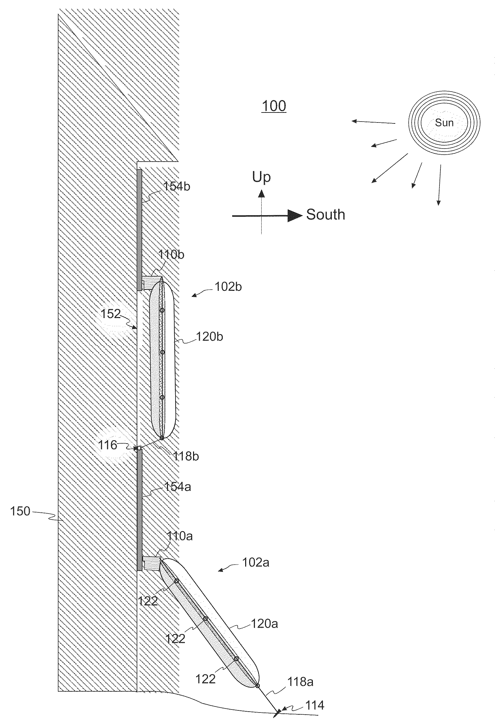
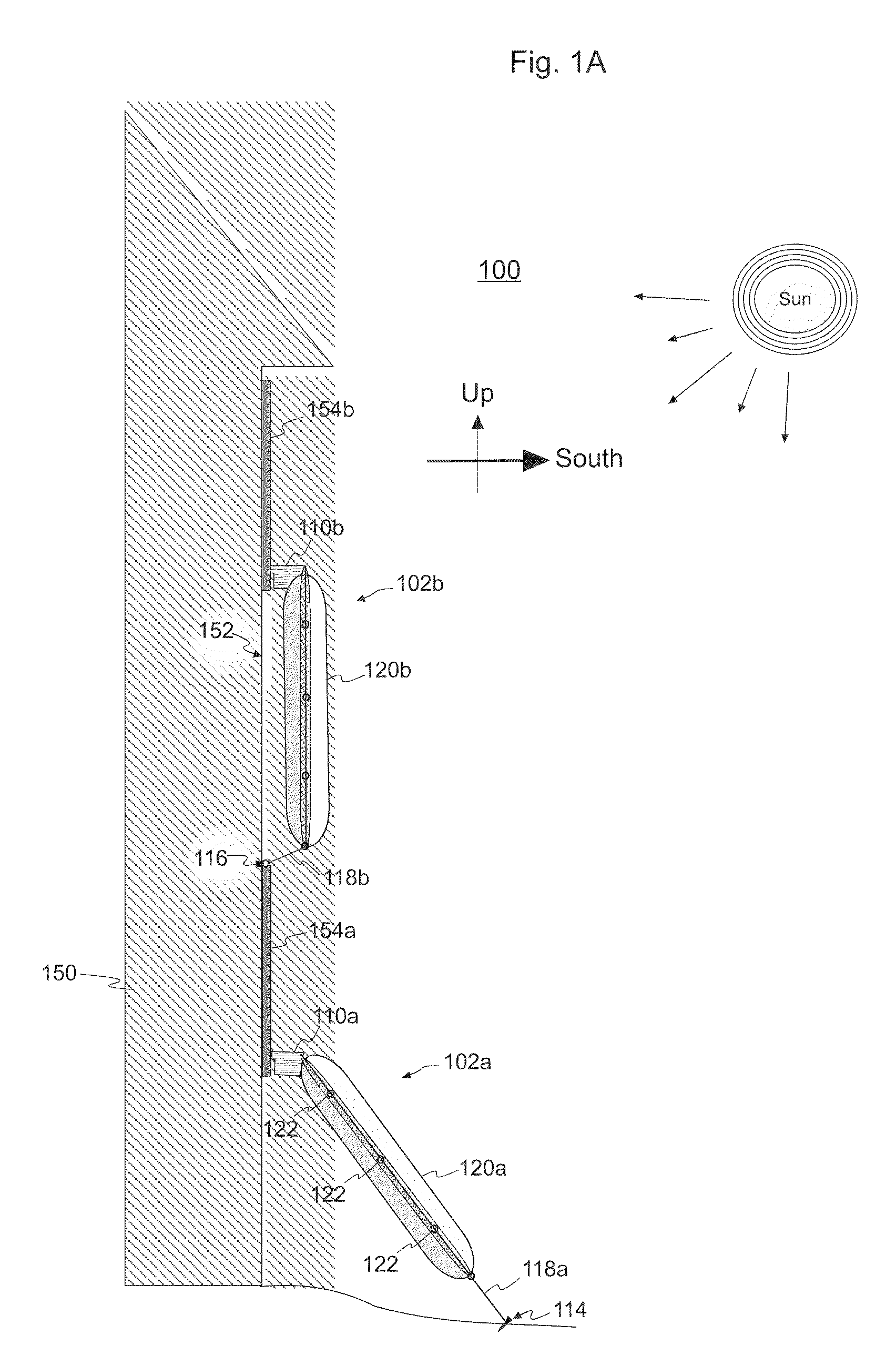
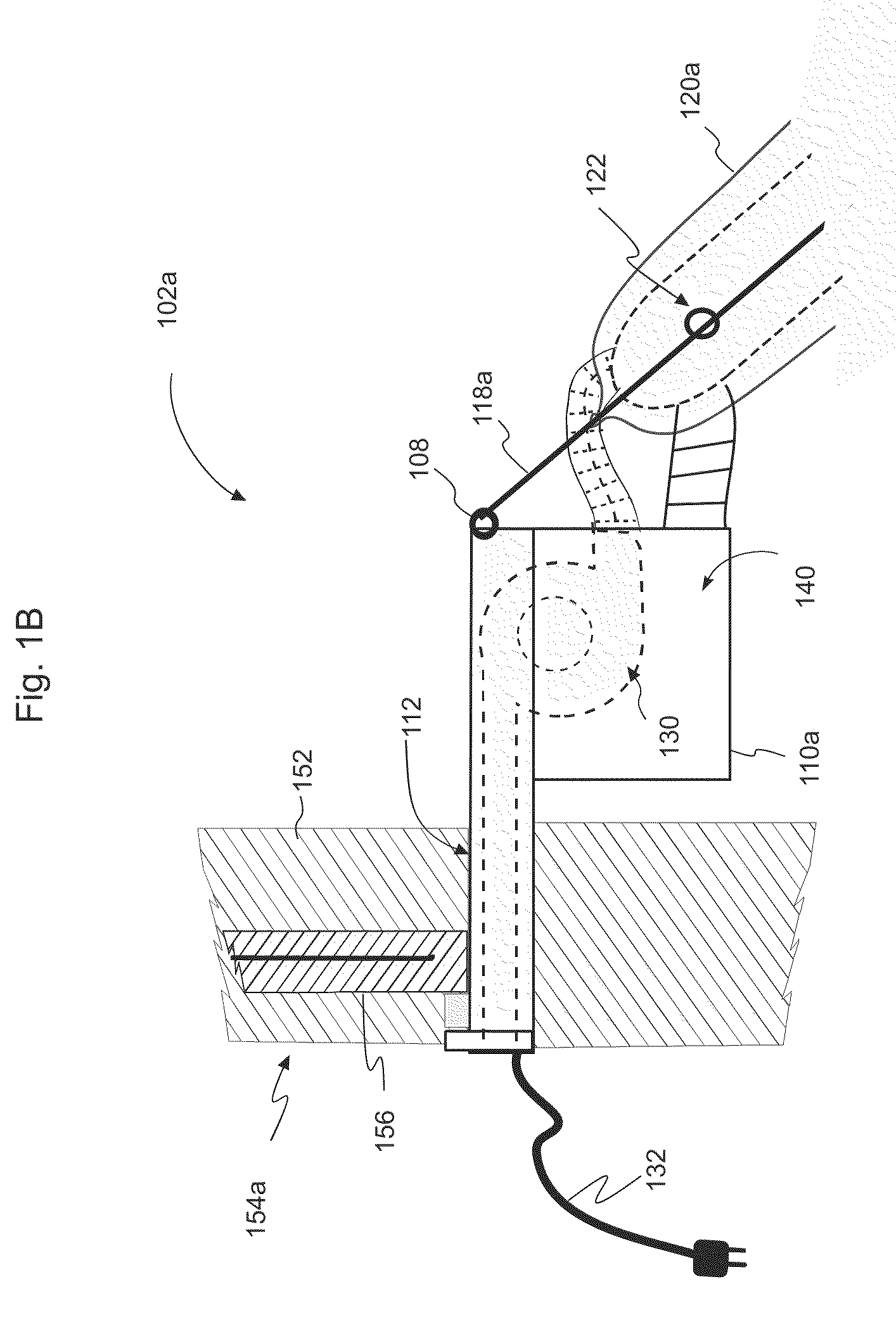
[0018]FIGS. 1A-B show diagrammatic views of a solar-heating system 100 having two substantially analogous solar-heating units 102a and 102b according to one embodiment of the invention. More specifically, FIG. 1A shows each of solar-heating units 102a and 102b deployed at the exterior of a structure (e.g., a house) 150. FIG. 1B shows an enlarged cross-sectional view of a portion of solar-heating unit 102a. Although each of solar-heating units 102a and 102b can be deployed at any suitable location adjacent to structure 150, a location that can maximize the amount of solar energy collected by the solar-heating unit, such as a wall 152 with a southern exposure (in the Northern Hemisphere), is generally preferred.

[0019]Solar-heating unit 102 has a housing 110 and an inflatable solar collector 120 that is operatively connected to the housing. In general, housing 110 can be mounted in any suitable opening in a wall or roof of structure 150. For example, housing 110a of solar-heating unit ...


PUM


Abstract

A solar-heating system having an inflatable solar collector connected to a housing that can be installed, e.g., in a sash window of a house. The housing has an air blower that draws air from the interior of the house and directs it into the inflatable solar collector, which is positioned outside the window. The collector has a flexible permeable membrane that serves as a transpired absorber of solar radiation. The air flowing through the collector is heated when it percolates through the membrane exposed to solar light. The heated air is returned back to the interior of the house, thereby providing space heating. In certain embodiments, in addition to serving as a transpired absorber, the membrane can also serve as an air filter that removes particles, odor-causing pollutants, and/or allergens from the drawn air.

Description

CROSS-REFERENCE TO RELATED APPLICATIONS[0001]This application claims priority from U.S. Provisional Patent Application Ser. No. 61 / 107,738 filed on Oct. 23, 2008, and entitled “Portable Solar Heating Apparatus for Window Installations Having an Inflatable Solar Collector,” which is incorporated herein by reference in its entirety.BACKGROUND[0002]1. Field of the Invention[0003]The present invention relates to solar-energy utilization and, more specifically, to solar-heating systems.[0004]2. Description of the Related Art[0005]This section introduces aspects that may help facilitate a better understanding of the invention(s). Accordingly, the statements of this section are to be read in this light and are not to be understood as admissions about what is in the prior art or what is not in the prior art.[0006]Heating, ventilation, and air conditioning (HVAC) systems account for about one half of the energy used in residential buildings in the United States. Solar HVAC technologies can b...

Claims


Application Information

Patent Timeline
Patent Type & Authority Applications(United States)
IPC IPC(8): F24J2/36F24J2/04
CPCF24J2/0433Y02E10/44Y02B10/20F24J2/243F24S10/73F24S20/63
Inventor PELLEGRINO, STEPHEN T.
Owner PELLEGRINO STEPHEN T
Why Eureka
Try Eureka