Brake caliper including heat pipes

a technology of brake calipers and heat pipes, which is applied in the direction of axially engaging brakes, slack adjusters, braking elements, etc., can solve the problems of brake fluid boiling, brake pads to heat, and number of problems

Inactive Publication Date: 2010-04-29
FINKEL BRIAN G
View PDF24 Cites 33 Cited by
  • Summary
  • Abstract
  • Description
  • Claims
  • Application Information

AI Technical Summary

Benefits of technology

[0010]In another embodiment, a disk brake is provided. The disk brake includes a brake caliper having piston bores and one or more heat pipes. The heat pipes are at least partially embedded within the brake caliper. In operation, the heat pipes transfer heat away from the piston bores thereby cooling brake fluid in the piston bores.

Problems solved by technology

When the brake pads contact opposite sides of the brake rotor, friction causes the brake pads to heat.
However, if the brake fluid or brake caliper overheat, then a number of problems may occur.
If the brake fluid overheats, the brake fluid may boil and reduce the braking efficiency of a motor vehicle.
Typically, regular brake fluid boils at about 350° F. A high-temperature brake fluid usually boils between 400 and 500° F. In addition, if the brake fluid overheats then the brake caliper may experience excessive wear or damage, thus reducing the life of the brake caliper.
Furthermore, if the brake fluid overheats, the brake may fail and endanger the driver of the vehicle as well as another driver or pedestrian.
For example, the brake fluid may overheat and cause the driver of the vehicle to experience dead pedal.
If the brake caliper overheats, the brake caliper may excessively heat and increase the pressure of a tire in the vehicle.
In addition, tire pressure can impact the fuel economy of the vehicle.
The brake caliper can reach temperatures as high as 500° F., which can increase the pressure of the tire and reduce the driver's ability to handle the vehicle.
In addition, if the brake caliper excessively heats the tire, then the tire may melt and cause the tire to blow out, which could endanger the lives of others as well as reduce the performance of the vehicle.

Method used


Image

  • Brake caliper including heat pipes
  • Brake caliper including heat pipes
  • Brake caliper including heat pipes

Examples


Embodiment Construction

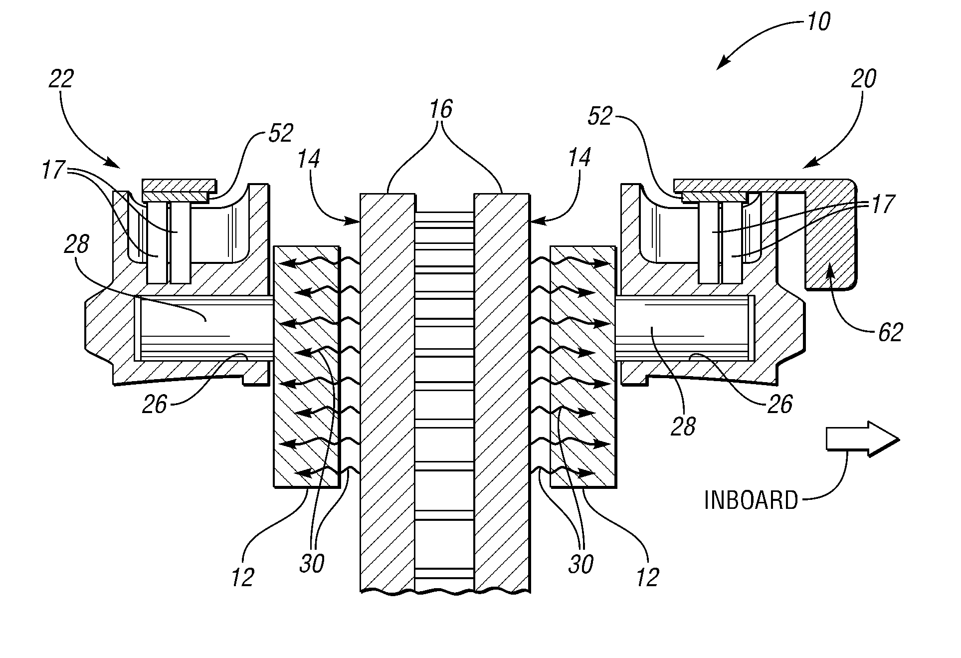
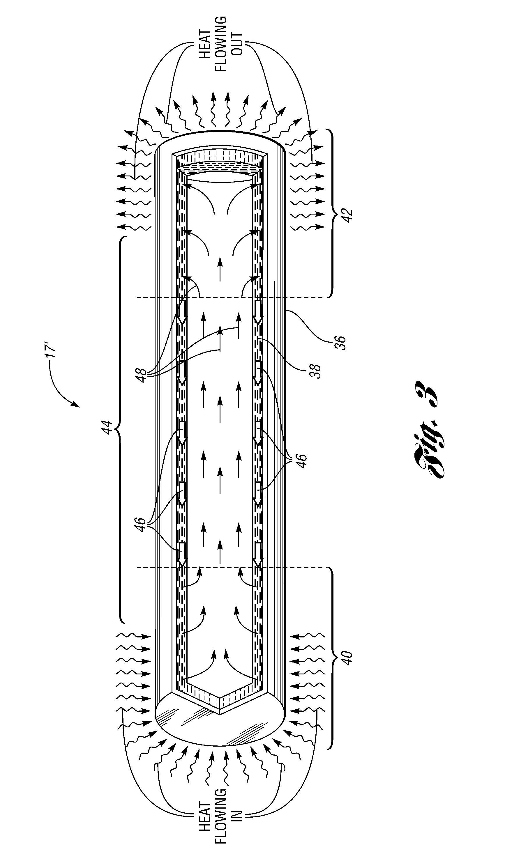
[0020]Embodiments of the present invention generally provide a brake caliper including heat pipes for cooling the brake caliper as well as the brake fluid in the brake caliper. The heat pipes cool the brake fluid in the piston bores. In addition, the heat pipes may cool the brake fluid in other portions of the brake caliper, such as the brake fluid flowing through a fluid passage in the brake caliper.

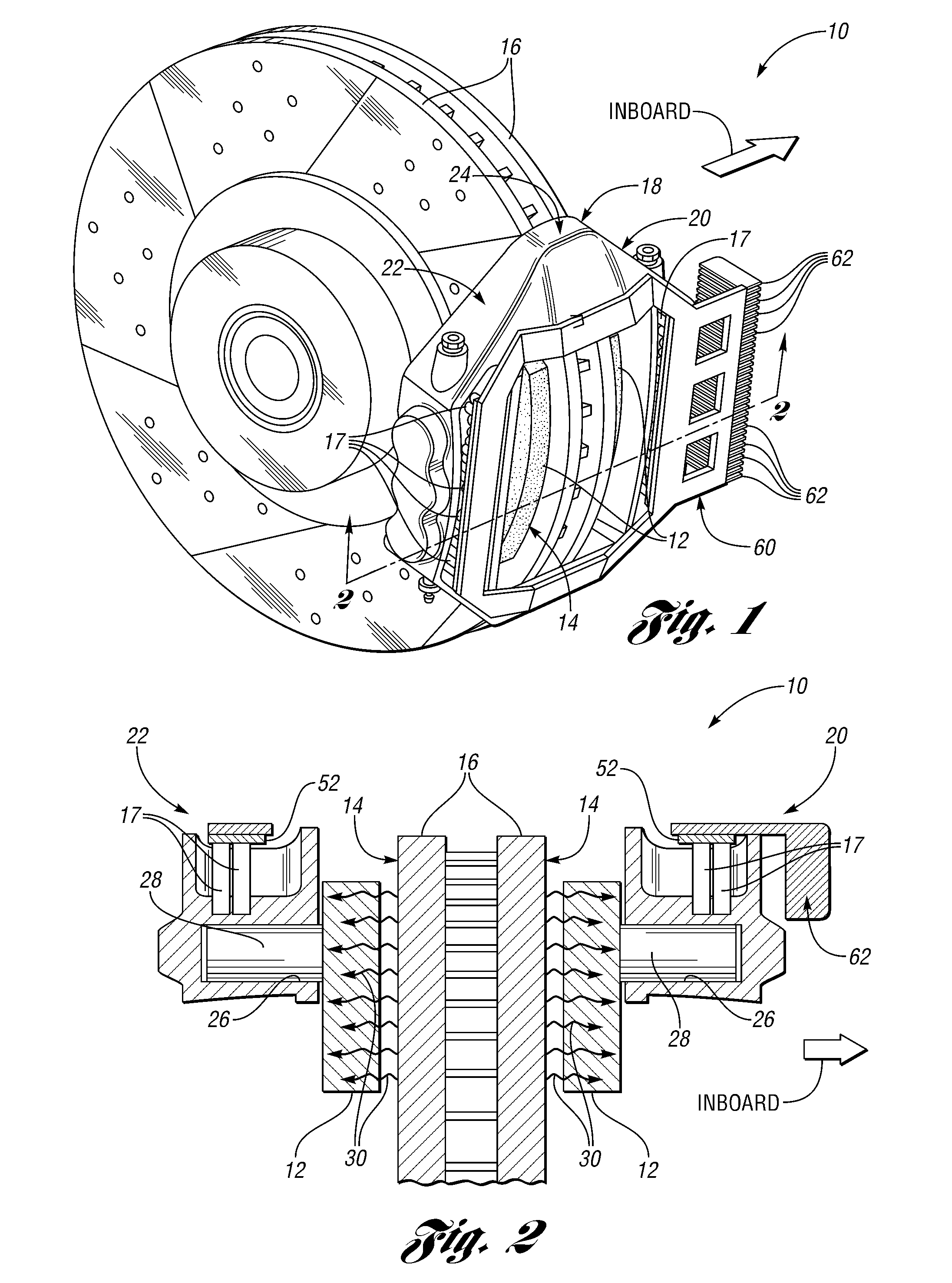
[0021]With reference to FIG. 1, a brake caliper 10 receives brake pads 12 and a periphery 14 of a brake rotor 16. The brake caliper 10 includes heat pipes 17 and a caliper body 18. The caliper body 18 includes an inboard portion 20, an outboard portion 22, and a connector 24. During use, the inboard portion 20 faces toward the inside of a vehicle as indicated by the arrow labeled “INBOARD” while the outboard portion 22 faces toward the outside of the vehicle, which is in the opposite direction of the inboard portion 20 or “rim side” of the brake rotor 16. Either the inboard portion 20, ...


PUM


Abstract

A brake caliper including a caliper body and heat pipes at least partially embedded within the caliper body. The caliper body includes spaced inboard and outboard portions. In addition, at least one of the portions includes piston bores. The caliper body further includes a connector between the inboard and outboard portions whose spacing permits brake pads and a periphery of a brake rotor to be received between the inboard and outboard portions. Also, the brake caliper includes pistons disposed in the piston bores to press the brake pads against the periphery of the brake rotor when brake fluid moves the pistons and the brake pads toward the brake rotor. As the brake pads heat the brake caliper, the heat pipes transfer heat away from the piston bores thereby cooling the brake caliper and brake fluid in, around, or near the piston bores.

Description

BACKGROUND[0001]1. Field of the Invention[0002]Embodiments of the present invention relate to a brake caliper including heat pipes for a brake.[0003]2. Background Art[0004]Disk type brakes include a brake caliper, brake pads, and a brake rotor. When the brake pads contact opposite sides of the brake rotor, friction causes the brake pads to heat. The brake pads can reach temperatures over 700° F. As the temperature of the brake pads increases, heat transfers from the brake pads to one or more pistons in the brake caliper. As a result, the brake caliper and brake fluid heat to higher temperatures. However, if the brake fluid or brake caliper overheat, then a number of problems may occur.[0005]If the brake fluid overheats, the brake fluid may boil and reduce the braking efficiency of a motor vehicle. Typically, regular brake fluid boils at about 350° F. A high-temperature brake fluid usually boils between 400 and 500° F. In addition, if the brake fluid overheats then the brake caliper ...

Claims


Application Information

Patent Timeline
Patent Type & Authority Applications(United States)
IPC IPC(8): F16D55/02F16D65/827
CPCF16D65/847F16D2065/781F16D2055/0091F16D2055/0016F16D2065/789
Inventor FINKEL, BRIAN G.
Owner FINKEL BRIAN G
Why Eureka
Try Eureka