Backup transmission structure of electronic device

a transmission structure and electronic device technology, applied in the field of back-up transmission structure, can solve the problems of difficult maintenance and troubleshooting of terminal equipment, and achieve the effect of improving the stability of signal transmission

Inactive Publication Date: 2010-04-29
ZIPPY TECH
View PDF2 Cites 2 Cited by
  • Summary
  • Abstract
  • Description
  • Claims
  • Application Information

AI Technical Summary

Benefits of technology

[0007]Compared with the prior art, the present invention improves the stability of a signal transmission between the host equipment and the terminal equipment.

Problems solved by technology

Furthermore, it is difficult to troubleshoot the failed terminal equipment 20 among so many terminal equipment 20 of the electronic device, and the prior art brings up the issue of difficult maintenance.

Method used


Image

  • Backup transmission structure of electronic device
  • Backup transmission structure of electronic device
  • Backup transmission structure of electronic device

Examples


Embodiment Construction

[0011]The technical characteristics of the present invention will become apparent with the detailed description of preferred embodiments accompanied with related drawings as follows:

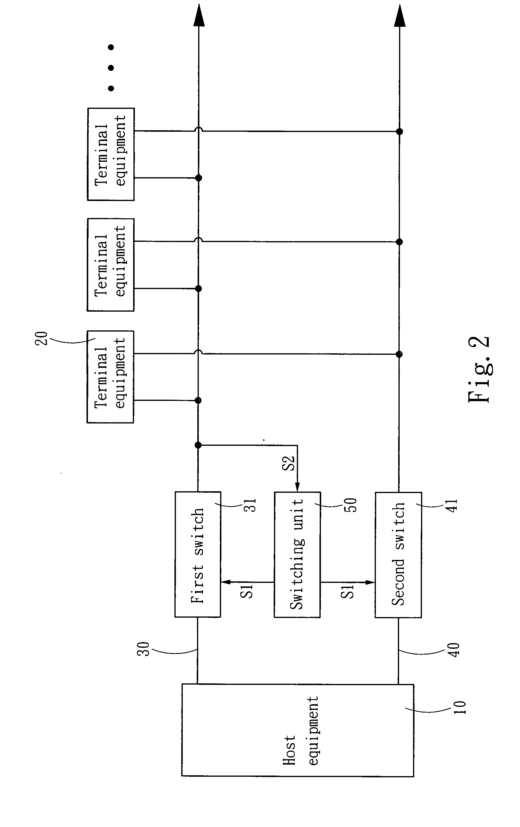
[0012]With reference to FIG. 2 for a backup transmission structure of an electronic device in accordance with the present invention, the transmission structure is electrically coupled to a host equipment 10 and at least one terminal equipment 20, and comprises at least two transmission circuits, namely a primary transmission circuit 30 and a backup transmission circuit 40 electrically coupled to the host equipment 10 and the terminal equipment 20. The primary transmission circuit 30 and the backup transmission circuit 40 include a first switch 31 and a second switch 41 thereon respectively. The transmission structure further comprises a switching unit 50 electrically coupled to the first switch 31 and the second switch 41 for normally outputting an ON signal S1 to the first switch 31 to connect the prima...


PUM


Abstract

A backup transmission structure of an electronic device includes a switching unit, and primary and backup transmission circuits connected to host and terminal equipment respectively. The primary and backup transmission circuits include first and second switches respectively. The switching unit normally outputs an ON signal to the first switch to connect the primary transmission circuit for an electric connection of the host and terminal equipment. The primary transmission circuit obtains a circuit disable signal to switch outputting the ON signal to the second switch for electrically connecting the backup transmission circuit, so as to maintain an electric connection between the host equipment and the terminal equipment, and improve the stability of signal transmissions between the host equipment and the terminal equipment to overcome the shortcomings of the prior art adopting a host equipment that uses a single transmission circuit to connect terminal equipment in series and resulting in frequent breakdowns.

Description

FIELD OF THE INVENTION[0001]The present invention relates to a backup transmission structure, and more particularly to a backup transmission structure applied in an electronic device for maintaining signal transmissions between host and terminal equipment.BACKGROUND OF THE INVENTION[0002]As science and technology advance rapidly and various different electronic products such as computers, mobile phones and digital cameras are introduced to the market constantly, the function of a product is a major factor for consumers to select the product. To meet consumers' requirements, manufacturers keep adding functions to improve the add-on value of the products. These electronic products install a considerable number of electronic components to achieve multifunctional effect, and thus it is an important subject for manufacturers of the related industry to effectively integrate the electronic components into the electronic device to maintain a normal operation of the electronic device.[0003]A...

Claims


Application Information

Patent Timeline
Patent Type & Authority Applications(United States)
IPC IPC(8): H04L12/40
CPCH04L12/40189
Inventor CHEN, TSUNG-CHUN
Owner ZIPPY TECH
Why Eureka
Try Eureka