Spring probe

a probe and spring technology, applied in the field of probes for probe cards, can solve the problems of inability to bear large electric current, inability to improve the transmission bandwidth of signals passing through the spring section, and inability to carry large electric current, so as to prevent the spring section of the spring sleeve from fracturing, and improve the stability of signal transmission

Inactive Publication Date: 2017-01-03
MPI CORP
View PDF13 Cites 2 Cited by
  • Summary
  • Abstract
  • Description
  • Claims
  • Application Information

AI Technical Summary

Benefits of technology

[0010]The present invention has been accomplished in view of the above-noted circumstances. It is an objective of the present invention to provide a spring probe, which can effectively prevent signals from being transmitted through the spring section of the spring sleeve, thereby improving the stability of signal transmission and preventing the spring section of the spring sleeve from fracture.

Problems solved by technology

Therefore, the testing signals are likely transmitted between the connection section 132 and the needle 12 and transmitted through the spring sections 138, resulting in unstable signal transmission.
Besides, because the spring sections 138 have small cross section area, they are unable to bear large electric current.
In addition, because the spring sections 138 have relatively longer path for signal transmission, the spring sections 138 may have great inductance, such that the transmitting bandwidth of the signals passing through the spring sections can hardly be improved.
As a result, the conventional spring probe 11 is unsuitable for high frequency testing.

Method used


Image

  • Spring probe
  • Spring probe
  • Spring probe

Examples


Embodiment Construction

[0035]First of all, it is to be mentioned that same reference numerals used in the following preferred embodiments and the appendix drawings designate same or similar elements throughout the specification for the purpose of concise illustration of the present invention. Besides, the drawings of the following embodiments are provided only for the convenience of illustrating the technical features of the present invention, and therefore not drawn to the real scale.

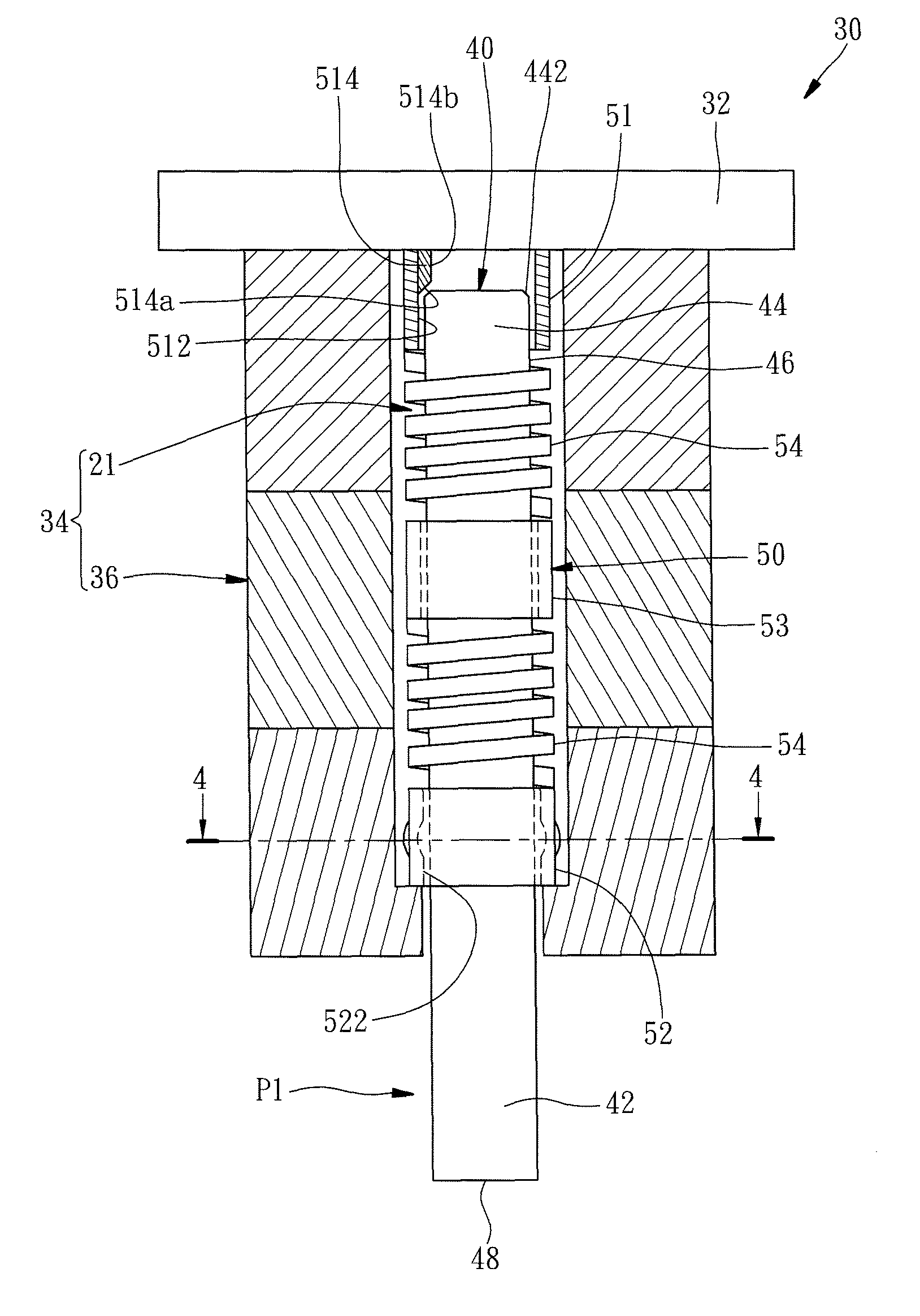
[0036]Referring to FIG. 3, a spring probe 21 according to a first preferred embodiment of the present invention is adapted for being used in a probe card 30 which comprises a circuit board 32 and a probe device 34. The probe device 34 comprises a probe seat 36, and the spring probe 21 installed in the probe seat 36. The amount of the spring probes 21 that are installed in the probe seat 36 of the probe device 34 is unlimited. The circuit board 32 and the probe seat 36 are the same with that of the conventional probe card and...


PUM


Abstract

A spring probe includes a needle, a spring sleeve sleeved onto the needle, and a protrusion. The spring sleeve has upper and lower non-spring sections, and at least a spring section therebetween. The needle has a bottom end portion protruding out from the lower non-spring section, and a top end portion located in the upper non-spring section. The protrusion is located at one of the top end portion and the upper non-spring section. The needle is movable relative to the upper non-spring section from an initial position to a connected position where the upper non-spring section is electrically connected with the needle through the protrusion when receiving an external force. As a result, the spring probe effectively prevents signals from being transmitted through the spring section, thereby improving stability of signal transmission and preventing the spring section from fracture.

Description

BACKGROUND OF THE INVENTION[0001]1. Field of the Invention[0002]The present invention relates generally to probes for probe cards and more particularly, to a spring probe.[0003]2. Description of the Related Art[0004]Upon testing semiconductor chips, a tester is electrically connected with devices under test (hereinafter referred to as the “DUTs”) through a probe card, so that the tester can obtain the testing results of the DUTs by means of signal transmission and analysis. The conventional probe card is usually composed of a circuit board and a probe device, or further comprises a space transformer disposed between the circuit board and the probe device. The probe device has a plurality of probes arranged corresponding to contact pads of the DUTs, so that the contact pads can be probed by the probes at the same time.[0005]FIG. 1 is an exploded plan view of a conventional spring probe 11 which comprises a needle 12, and a spring sleeve 13 sleeved onto the needle 12. FIG. 2 is a sche...

Claims


Application Information

Patent Timeline
Patent Type & Authority Patents(United States)
IPC IPC(8): G01R1/067G01R1/073
CPCG01R1/06722G01R1/07307
Inventor KUO, TING-HSINCHEN, TSUNG-YILI, TIEN-CHIALEE, YI-LUNGWU, CHIEN-CHOU
Owner MPI CORP
Why Eureka
Try Eureka