Method of treating a beverage bottle filling machine in a beverage bottling plant, method of cleaning a container filling machine in a container filling plant, and arrangements therefor

a beverage bottle and filling machine technology, applied in liquid handling, instruments, packaged goods types, etc., can solve the problems that the mode of operation so far cannot be used with free-stream filling systems, and the product flow cannot be influenced by a return gas regulating system

Inactive Publication Date: 2010-05-06
KHS GMBH
View PDF10 Cites 19 Cited by
  • Summary
  • Abstract
  • Description
  • Claims
  • Application Information

AI Technical Summary

Benefits of technology

[0010]To solve this problem, the present application discloses a free-stream filling system for filling machines for filling of bottles or similar containers with a liquid product. The free-stream filling system comprises a filling element, in whose housing is provided a liquid channel controlled by at least one liquid valve and forming at least one dispensing opening, in which is arranged at least one gas lock after the at least one liquid valve in the flow direction of the liquid product during the filling and through which the liquid product flows during the filling. The filling system additionally comprises a holder on which a closure element closing the dispensing opening for a cleaning and/or sterilization operation is or can be secured, and also with

Problems solved by technology

This mode of operation thus far could not be used with free-stream filling systems.
Furthermore, the product flow

Method used


Image

  • Method of treating a beverage bottle filling machine in a beverage bottling plant, method of cleaning a container filling machine in a container filling plant, and arrangements therefor
  • Method of treating a beverage bottle filling machine in a beverage bottling plant, method of cleaning a container filling machine in a container filling plant, and arrangements therefor
  • Method of treating a beverage bottle filling machine in a beverage bottling plant, method of cleaning a container filling machine in a container filling plant, and arrangements therefor

Examples


Embodiment Construction

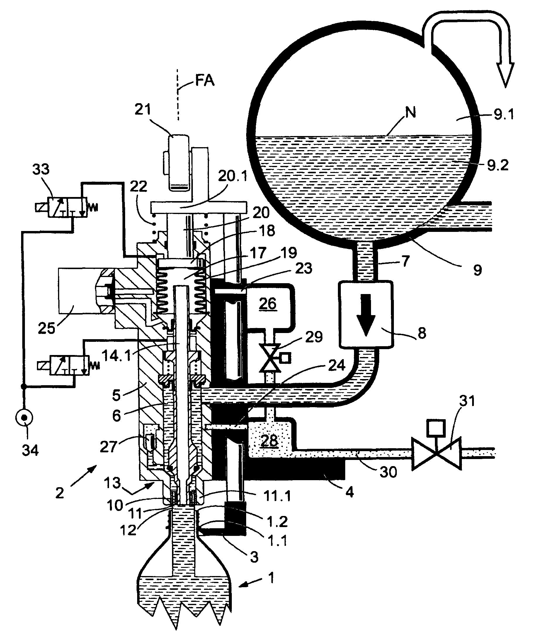
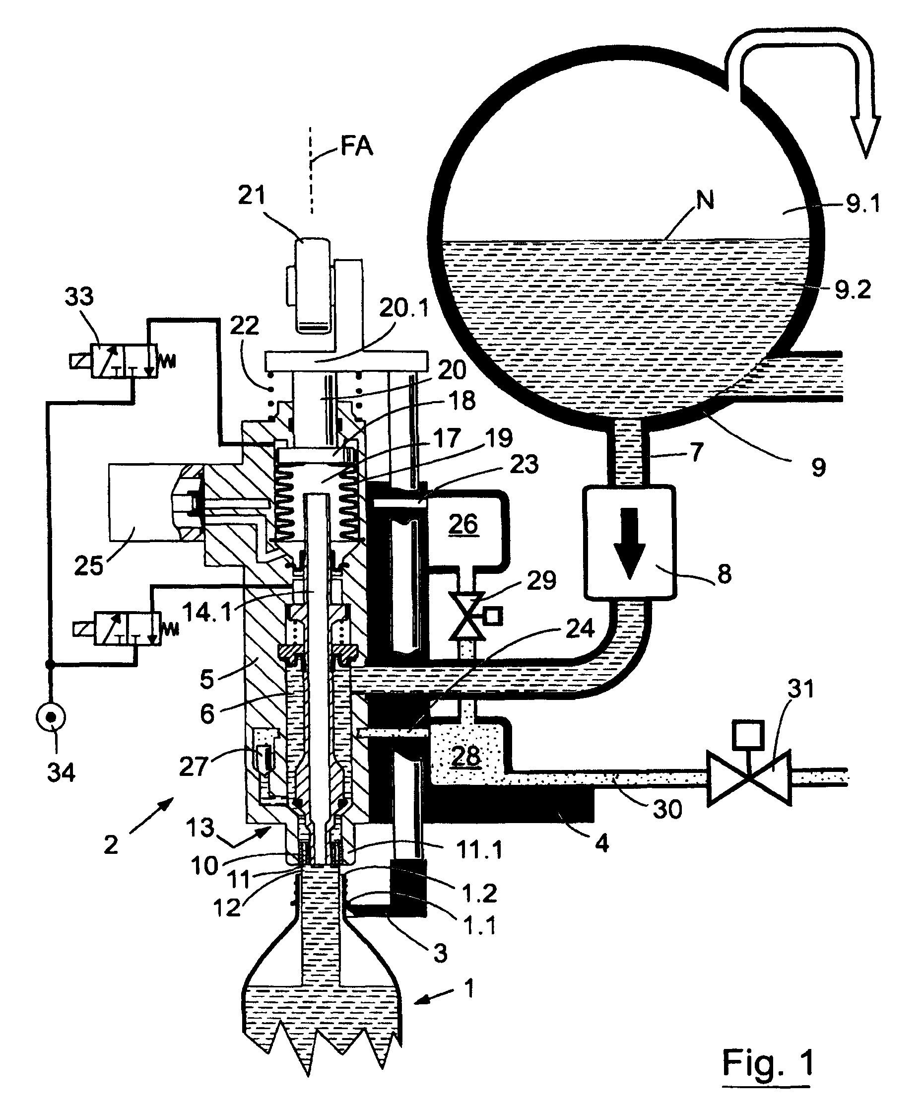
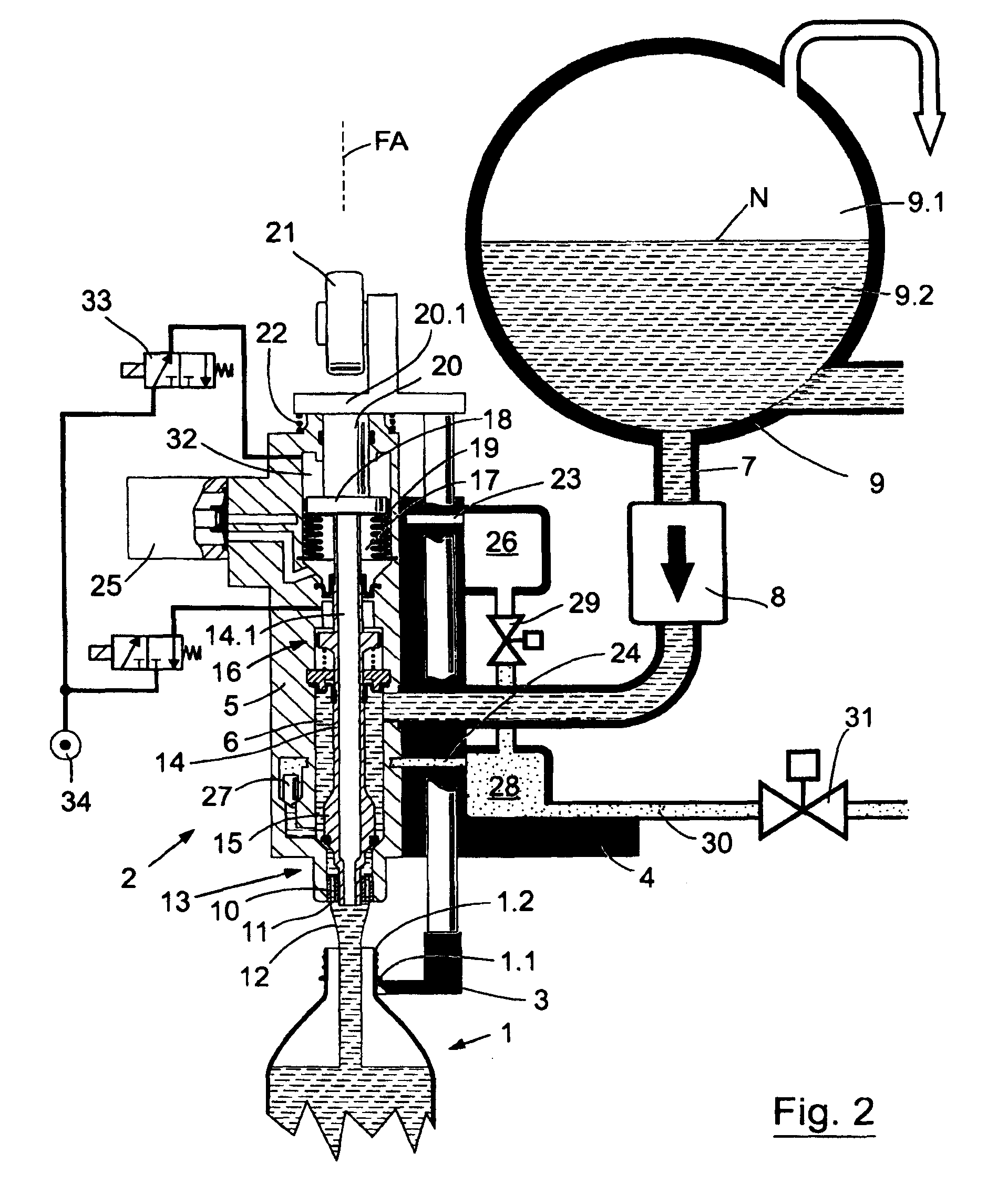
[0021]The free-stream filling system depicted in FIGS. 1 and 2 is part of a filling machine, such as a filling machine of rotary design for free-stream filling of bottles 1 or other containers with a liquid product. The filling system comprises a filling element 2, which is provided along with several identical filling elements 2 and coordinated bottle or container holders 3, from which the bottles 1 being filled are suspended by a mouth flange 1.1 during the filling process, at the periphery of a rotor 4 which can be driven in rotation about a vertical axis of the machine.

[0022]In the housing 5 of each filling element 2 there is formed a liquid channel 6, which is connected by its upper end via a conduit 7 with flow meter 8 to a kettle 9 provided on the rotor 4 in common for the filling elements 2. The kettle 9 is filled with the liquid product under control up to a level N for the operation of the filling machine, so that a gas space 9.1 is formed in the kettle 9 above the level o...


PUM

PropertyMeasurementUnit
Timeaaaaaaaaaa
Pressureaaaaaaaaaa
Flow rateaaaaaaaaaa

Abstract

A method of treating a beverage bottle filling machine in a beverage bottling plant, method of cleaning a container filling machine in a container filling plant, and arrangements therefor. The abstract of the disclosure is submitted herewith as required by 37 C.F.R. §1.72(b). As stated in 37 C.F.R. §1.72(b): A brief abstract of the technical disclosure in the specification must commence on a separate sheet, preferably following the claims, under the heading “Abstract of the Disclosure.” The purpose of the abstract is to enable the Patent and Trademark Office and the public generally to determine quickly from a cursory inspection the nature and gist of the technical disclosure. The abstract shall not be used for interpreting the scope of the claims. Therefore, any statements made relating to the abstract are not intended to limit the claims in any manner and should not be interpreted as limiting the claims in any manner.

Description

CONTINUING APPLICATION DATA[0001]This application is a Continuation-In-Part application of International Patent Application No. PCT / EP2008 / 003403, filed on Apr. 26, 2008, which claims priority from Federal Republic of Germany Patent Application No. 10 2007 022 259.0, filed on May 9, 2007. International Patent Application No. PCT / EP2008 / 003403 was pending as of the filing date of this application. The United States was an elected state in International Patent Application No. PCT / EP2008 / 003403.BACKGROUND[0002]1. Technical Field[0003]The present application pertains to a free-stream filling system for filling machines for filling of bottles or similar containers with a liquid product. The free-stream filling system comprises a filling element, in whose housing is provided a liquid channel controlled by at least one liquid valve and forming at least one dispensing opening, in which is arranged at least one gas lock after the at least one liquid valve in the flow direction of the liquid ...

Claims


Application Information

Patent Timeline
IPC IPC(8): B65B3/04B67D7/06B67C3/00B67D7/60
CPCB67C3/004B67C3/001B67C3/045
Inventor CLUSSERATH, LUDWIG
Owner KHS GMBH
Why Eureka
Try Eureka