Method of treating the inside surfaces of a clean room and treating a rotary beverage bottle blow-molding arrangement and blow-molding beverage bottles from preforms and an arrangement for performing the method

a technology of clean room and inside surface, applied in the direction of electric/magnetic/electromagnetic heating, packaging goods, transportation and packaging, etc., can solve the problem of not being able to operate the blow molding machine in a sterile manner, and achieve the effect of increasing the radiation distribution in the area and reducing the number of emitters

Active Publication Date: 2010-04-15
KHS GMBH
View PDF35 Cites 54 Cited by
  • Summary
  • Abstract
  • Description
  • Claims
  • Application Information

AI Technical Summary

Benefits of technology

[0012]In at least one possible embodiment of the present application, in the case of a rotary blow molding machine, the radiation emitters are mounted on or at least one of the rotating elements so that the radiation emitter rotates with the carousel of the blow molding machine. In this way, the number of emitters can be reduced and the distribution of radiation in the area increased. In this case, at least one radiation emitter can be mounted on the carousel or star wheel supporting or supplying the blow molds, said radiation emitter rotating in normal operation with said carousel or star wheel.

Problems solved by technology

The processing steps can or may be carried out before or after the blow molding machine, as up to now it has not been possible to operate the blow molding machine itself in a sterile manner.

Method used


Image

  • Method of treating the inside surfaces of a clean room and treating a rotary beverage bottle blow-molding arrangement and blow-molding beverage bottles from preforms and an arrangement for performing the method
  • Method of treating the inside surfaces of a clean room and treating a rotary beverage bottle blow-molding arrangement and blow-molding beverage bottles from preforms and an arrangement for performing the method
  • Method of treating the inside surfaces of a clean room and treating a rotary beverage bottle blow-molding arrangement and blow-molding beverage bottles from preforms and an arrangement for performing the method

Examples


Embodiment Construction

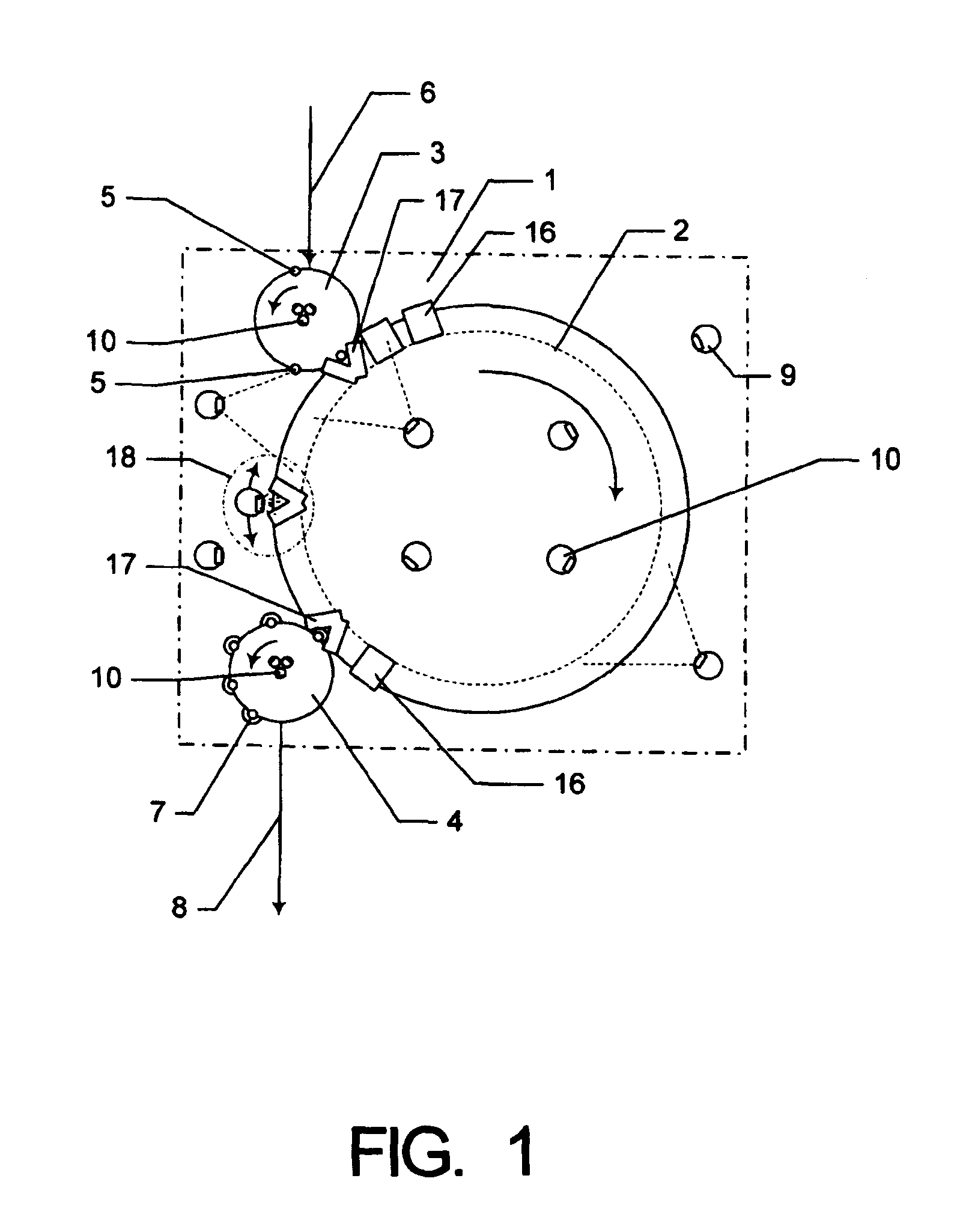
[0025]The container-producing apparatus 1, framed by the dot dash line, includes a carousel 2, a supply star 3 and an outlet star 4. Further details, such as a heating device, blow molds, etc. are known and are not represented in FIG. 1. The preforms 5 and the molded bottles 7 are conveyed first and foremost in a suspended manner, to which end they are retained at the neck in a known manner by means of grippers or holders (“neck handling”). The preforms 5 are supplied to the supply star 3 by means of the conveying path 6 and are transferred from said supply star to the carousel 2. Cavities 16 are positioned on the periphery of the carousel 2, said cavities for reasons of clarity being shown in a partial manner and the stretch / blow molding procedure being carried out in a known manner in said cavities. An open cavity 17 is shown opposite the supply star 3, and in the same way there is one opposite the outlet star 4, which takes over the full blown bottle.

[0026]After the blowing proce...


PUM

PropertyMeasurementUnit
vacuumaaaaaaaaaa
areaaaaaaaaaaa
positive electric-potentialaaaaaaaaaa

Abstract

A method of treating the inside surfaces of a clean room and treating a rotary beverage bottle blow-molding arrangement and blow-molding beverage bottles from preforms and an arrangement for performing the method. The abstract of the disclosure is submitted herewith as required by 37 C.F.R. §1.72(b). As stated in 37 C.F.R. §1.72(b): A brief abstract of the technical disclosure in the specification must commence on a separate sheet, preferably following the claims, under the heading “Abstract of the Disclosure.” The purpose of the abstract is to enable the Patent and Trademark Office and the public generally to determine quickly from a cursory inspection the nature and gist of the technical disclosure. The abstract shall not be used for interpreting the scope of the claims. Therefore, any statements made relating to the abstract are not intended to limit the claims in any manner and should not be interpreted as limiting the claims in any manner.

Description

[0001]This application is a Continuation-In-Part application of International Patent Application No. PCT / EP2008 / 002602, filed on Apr. 2, 2008, which claims priority from Federal Republic of Germany Patent Application No. 10 2007 017 938.5, filed on Apr. 13, 2007. International Patent Application No. PCT / EP2008 / 002602 was pending as of the filing date of this application. The United States was an elected state in International Patent Application No. PCT / EP2008 / 002602.BACKGROUND[0002]1. Technical Field[0003]The present application relates to a container-producing apparatus for producing plastics material containers from preforms, in one possible embodiment bottles, small receptacles (kegs) and other containers made from PET, said apparatus including a blow molding machine and suitable conveying devices, wherein at least one radiation emitter is mounted at the blow molding machine or on said blow molding machine and / or a radiation emitter is directed onto at least one part region of th...

Claims


Application Information

Patent Timeline
Patent Type & Authority Applications(United States)
IPC IPC(8): B65B3/02B65B65/00
CPCA61L2/087A61L2/10A61L2202/23B29K2067/00B29C49/36B29C49/42B29C2791/005B29C49/06B29C49/42095B29C49/42405B29C49/42418B29C49/42808B29C2949/0715
Inventor TILL, VOLKER
Owner KHS GMBH
Why Eureka
Try Eureka