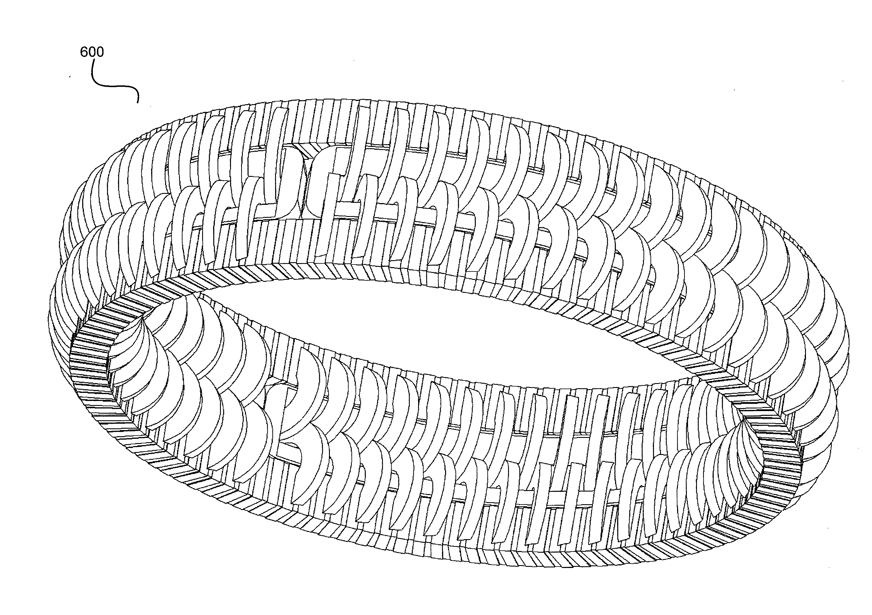
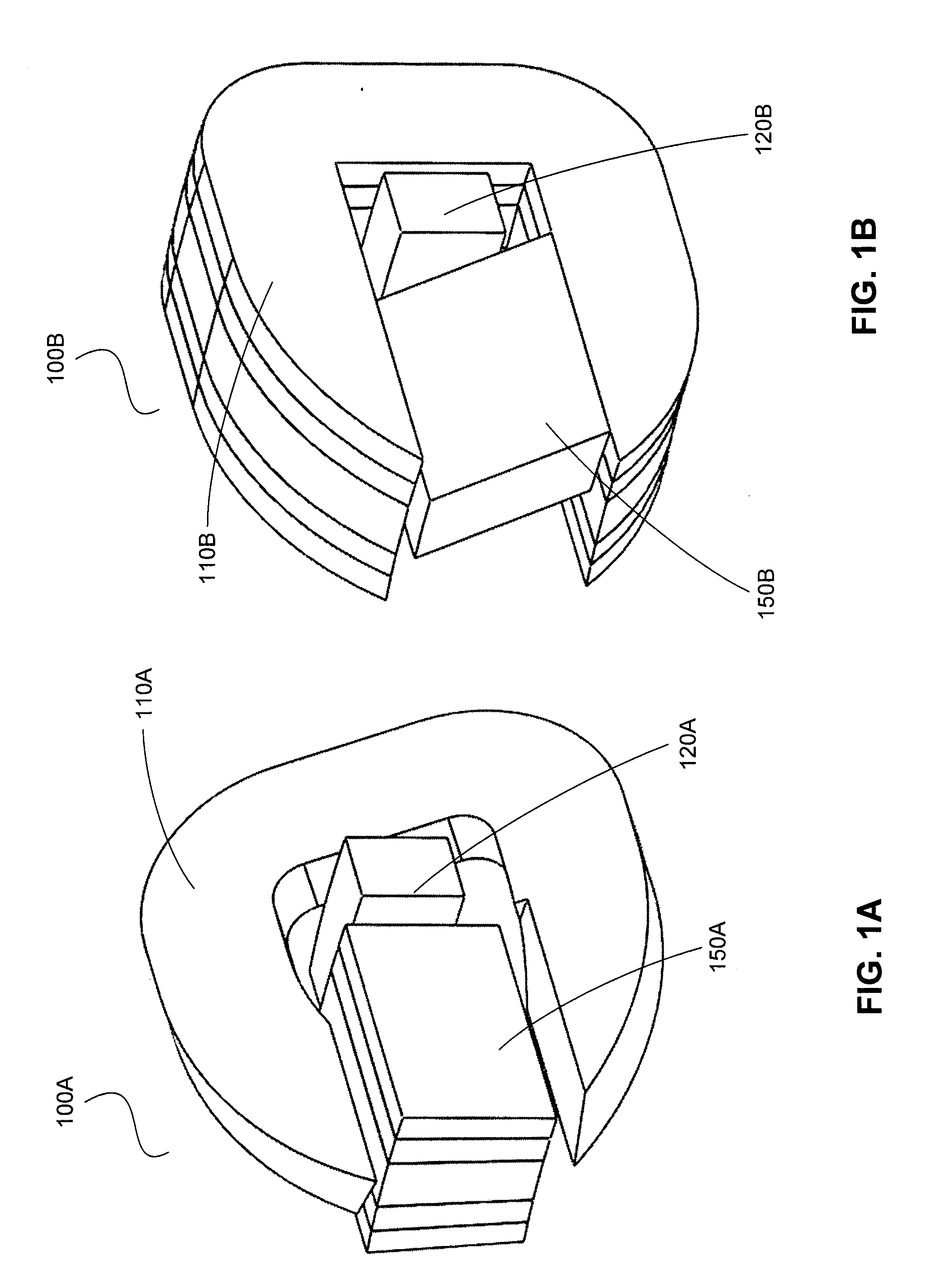
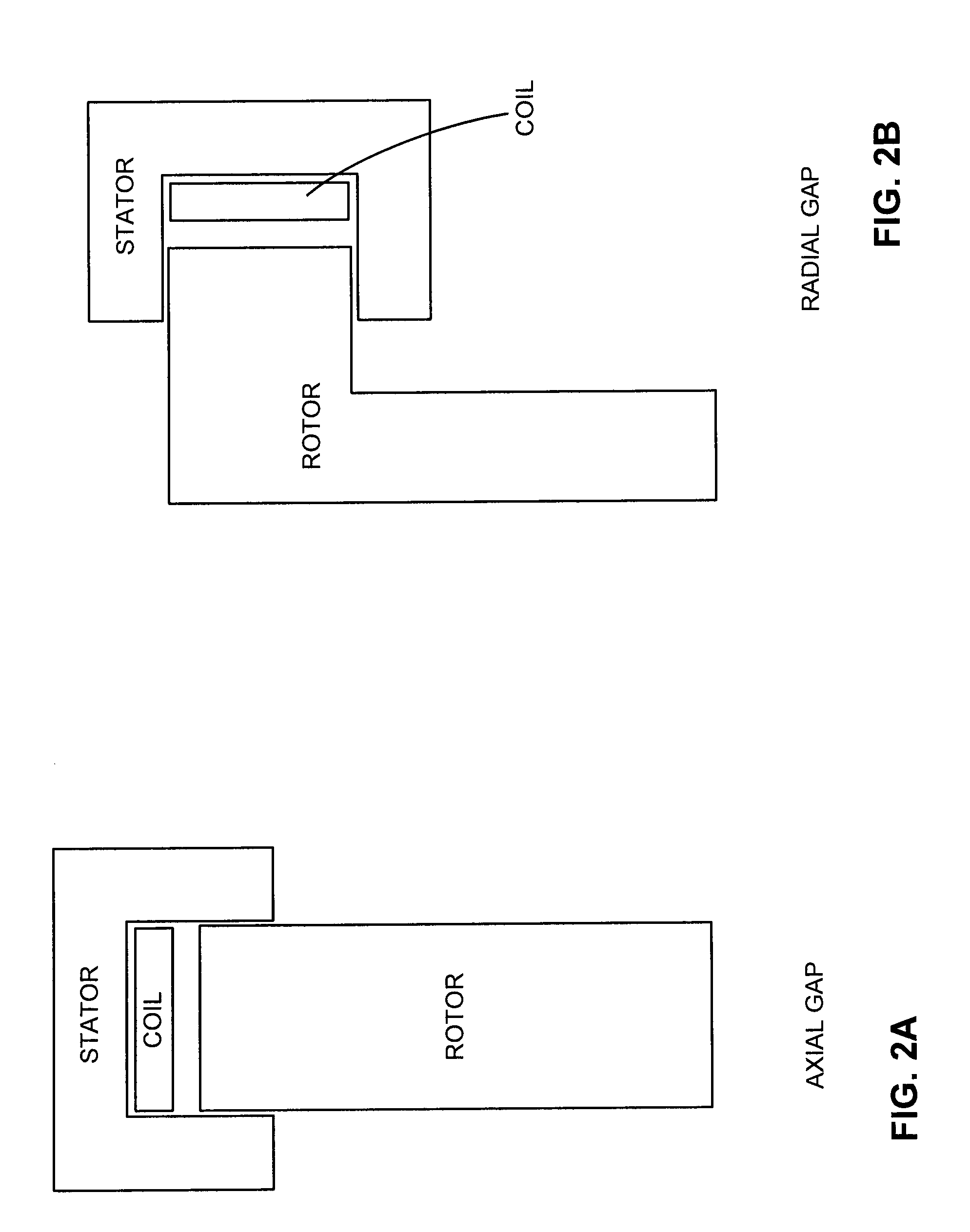
Polyphase transverse and/or commutated flux systems

a technology of commutated flux and transverse flux, applied in the field of electric systems, can solve the problems of increasing space requirements, increasing complexity, and reducing efficiency, and many applications that require lower rotational speeds

Active Publication Date: 2010-05-06
ELECTRIC TORQUE MASCH INC
View PDF99 Cites 18 Cited by
  • Summary
  • Abstract
  • Description
  • Claims
  • Application Information

AI Technical Summary

Problems solved by technology

However, many applications require lower rotational speeds.
Gear reduction reduces efficiency, adds complexity, adds weight, and adds space requirements.
Additionally, gear reduction increases system costs and increases mechanical failure rates.
Additionally, if a high rotational speed is not desired, and gear reduction is undesirable, then a motor or alternator typically must have a large number of poles to provide a higher electrical frequency at a lower rotational speed.
However, there is often a practical limit to the number of poles a particular motor or alternator can have, for example due to space limitations.

Method used


Image

  • Polyphase transverse and/or commutated flux systems
  • Polyphase transverse and/or commutated flux systems
  • Polyphase transverse and/or commutated flux systems

Examples


Embodiment Construction

[0041]The following description is of various exemplary embodiments only, and is not intended to limit the scope, applicability or configuration of the present disclosure in any way. Rather, the following description is intended to provide a convenient illustration for implementing various embodiments including the best mode. As will become apparent, various changes may be made in the function and arrangement of the elements described in these embodiments without departing from the scope of the appended claims.

[0042]For the sake of brevity, conventional techniques for electrical system construction, management, operation, measurement, optimization, and / or control, as well as conventional techniques for magnetic flux utilization, concentration, control, and / or management, may not be described in detail herein. Furthermore, the connecting lines shown in various figures contained herein are intended to represent exemplary functional relationships and / or physical couplings between vario...


PUM

PropertyMeasurementUnit
diameteraaaaaaaaaa
diameteraaaaaaaaaa
conductiveaaaaaaaaaa

Abstract

Disclosed are single- and poly-phase transverse and / or commutated flux machines and components thereof, and methods of making and using the same. Exemplary devices, including polyphase devices, may variously be configured with an interior rotor and / or an interior stator. Other exemplary devices, including polyphase devices, may be configured in a slim, stacked, and / or nested configuration. Via use of such polyphase configurations, transverse and / or commutated flux machines can achieve improved performance, efficiency, and / or be sized or otherwise configured for various applications.

Description

CROSS REFERENCE TO RELATED APPLICATIONS[0001]This application is a non-provisional of U.S. Provisional No. 61 / 110,874 filed on Nov. 3, 2008 and entitled “ELECTRICAL OUTPUT GENERATING AND DRIVEN ELECTRICAL DEVICES USING COMMUTATED FLUX AND METHODS OF MAKING AND USE THEREOF INCLUDING DEVICES WITH TRUNCATED STATOR PORTIONS.”[0002]This application is also a non-provisional of U.S. Provisional No. 61 / 110,879 filed on Nov. 3, 2008 and entitled “ELECTRICAL OUTPUT GENERATING AND DRIVEN ELECTRICAL DEVICES USING COMMUTATED FLUX AND METHODS OF MAKING AND USE THEREOF.”[0003]This application is also a non-provisional of U.S. Provisional No. 61 / 110,884 filed on Nov. 3, 2008 and entitled “METHODS OF MACHINING AND USING AMORPHOUS METALS OR OTHER MAGNETICALLY CONDUCTIVE MATERIALS INCLUDING TAPE WOUND TORROID MATERIAL FOR VARIOUS ELECTROMAGNETIC APPLICATIONS.”[0004]This application is also a non-provisional of U.S. Provisional No. 61 / 110,889 filed on Nov. 3, 2008 and entitled “MULTI-PHASE ELECTRICAL ...

Claims


Application Information

Patent Timeline
Patent Type & Authority Applications(United States)
IPC IPC(8): H02K37/02
CPCH02K1/02H02K1/04H02K1/246H02K37/02H02K41/025H02K2201/12H02K2201/15Y10T29/49012H02K21/26
Inventor CALLEY, DAVID G.JANECEK, THOMAS F.
Owner ELECTRIC TORQUE MASCH INC
Why Eureka
Try Eureka