
Image reading device and image forming apparatus

a reading device and image technology, applied in the direction of recording apparatus, electric apparatus casing/cabinet/drawer, instruments, etc., can solve the problems of increasing the driving force of the image reading unit, affecting the effect of the reading unit, and affecting the reading unit. , to achieve the effect of reducing the upward pushing for

Inactive Publication Date: 2010-05-06
KYOCERA DOCUMENT SOLUTIONS INC
View PDF1 Cites 8 Cited by
  • Summary
  • Abstract
  • Description
  • Claims
  • Application Information

AI Technical Summary

Benefits of technology

[0016]The present invention provides an image reading device which reduces the upward pushing force that is applied to an image reading unit because of the repulsive force generated by a cable trying to straighten itself.
[0017]The present invention provides an image reading device that is capable of reducing the repelling force generated by the cable trying to straighten itself out.

Problems solved by technology

However, the repulsive force that is generated by the cable trying to straighten itself acts as a force that pushes the image reading unit upwardly.
When the image reading unit is pushed upwardly, the image reading unit may be inclined or vertically moved, and the image reading unit therefore may not move smoothly.
Hence, in the typical image reading device, when the image reading unit is located in the home-position, a problem, such as a need to increase the driving force for moving the image reading unit, likely may occur.

Method used


Image

  • Image reading device and image forming apparatus
  • Image reading device and image forming apparatus
  • Image reading device and image forming apparatus

Examples


Embodiment Construction

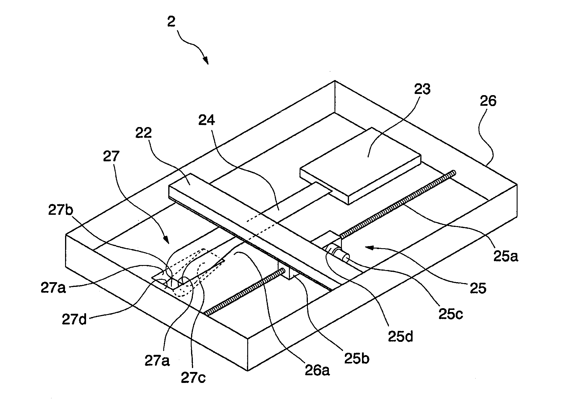
[0027]An image reading device according to an embodiment of the present invention will now be described below with reference to the drawings. In the following drawings, the drawings have been scaled with respect to the elements to illustrate the recognizable sizes of the elements. The following description provides a situation where the image reading device according to an embodiment of the present invention is installed in a copier, which is an example of an image forming apparatus. Also, the cable that is used in the embodiment is a flexible flat cable, however, the cable may be any other cable than a flexible flat cable.

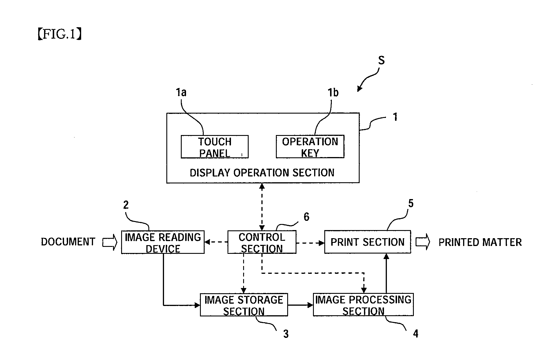
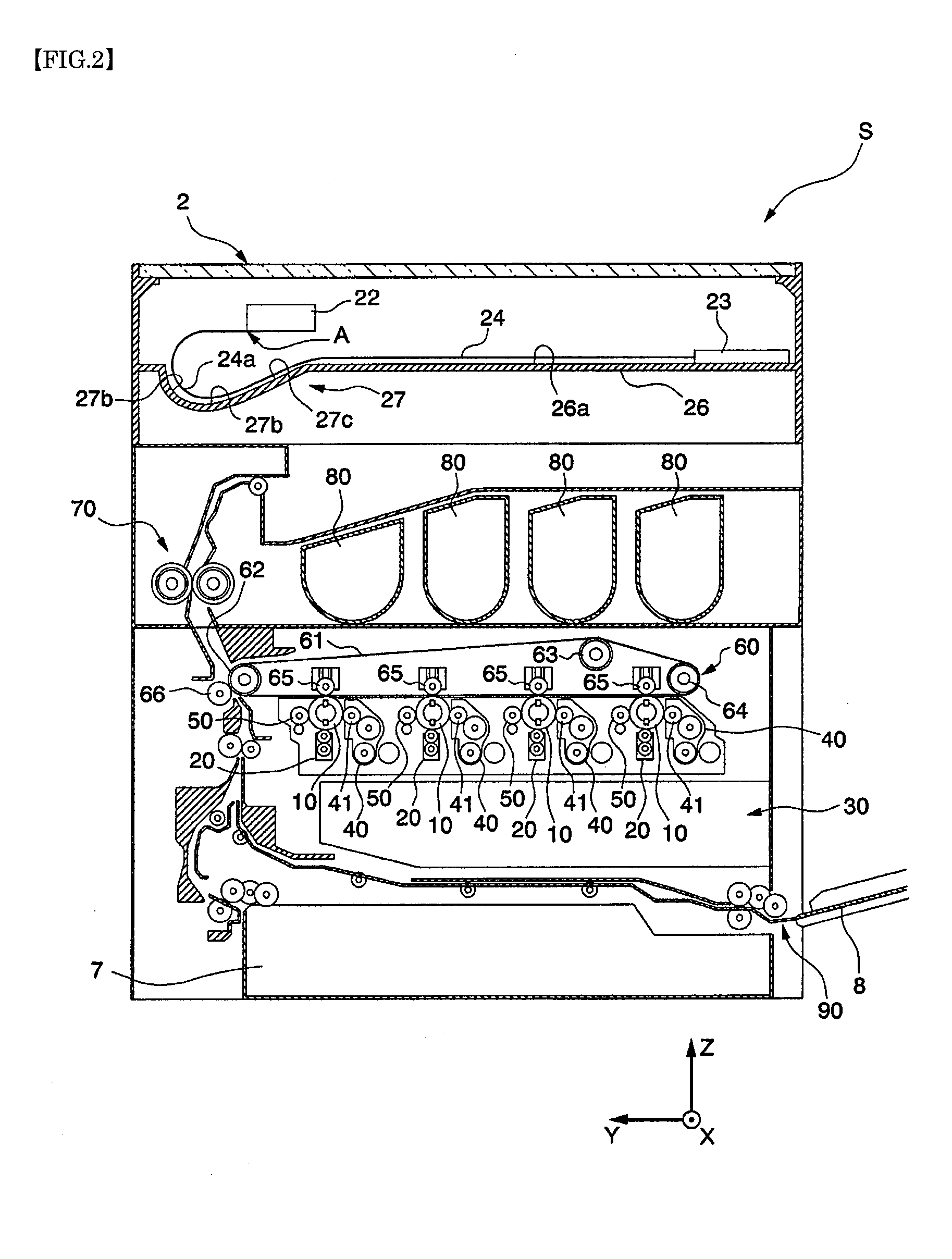
[0028]FIG. 1 is a functional block diagram showing a brief design of a copier S including an image reading device 2 of an embodiment. FIG. 2 is a cross-sectional view showing the design of the copier S.

[0029]Referring to FIG. 1, the copier S includes a display operation section 1, an image reading device 2, an image storage unit 3, an image processing unit 4, a pr...


PUM


Abstract

An image reading device having a recessed part which is located at a backward end with respect to a home-position of an image reading unit and extending downwardly with respect to a flat surface. When the image reading unit is located in the home-position, the recessed part receives a bent part of a flexible flat cable. With the image reading device, an upward pushing force applied to the image reading unit because of a repulsive force generated by the flexible flat cable trying to straighten itself is reduced.

Description

INCORPORATION BY REFERENCE[0001]This application is based upon and claims the benefit of priority from the corresponding Japanese Patent Application No. 2008-281140 filed Oct. 31, 2008, the entire contents of which are incorporated herein by reference.BACKGROUND[0002]1. Field of the Invention[0003]The present invention relates to image reading devices and image forming apparatuses, and more particularly to the handling of electrical transmission cables in such devices.[0004]2. Description of the Related Art[0005]The present invention relates to image reading devices which reads an image of a document and to image forming apparatuses.[0006]Conventionally, an image reading device, such as a scanner, typically uses a configuration wherein an image of a document that is placed on a document reading surface is read while an image reading unit is moved in a space below the document reading surface.[0007]In such an image reading device, a fixed unit is positioned in a casing. The fixed uni...

Claims


Application Information

Patent Timeline
IPC IPC(8): B41J2/435H05K5/00
CPCG03G2215/00198G03G2221/16H04N1/00519H04N1/00559H04N1/0083G03G21/1661
Inventor KAWAMOTO, MASUOITO, HIROSHI
Owner KYOCERA DOCUMENT SOLUTIONS INC
Learn More