Fluid mixing control device for a multi-fluid delivery system

a control device and flue gas technology, applied in the direction of infusion syringes, process and machine control, instruments, etc., can solve the problems of low-tech known “mixing” solutions, inability to provide such a capability of hand control devices in the market today, and limited injector equipment that might permit mixing

Active Publication Date: 2010-05-06
BAYER HEALTHCARE LLC
View PDF100 Cites 24 Cited by
  • Summary
  • Abstract
  • Description
  • Claims
  • Application Information

AI Technical Summary

Benefits of technology

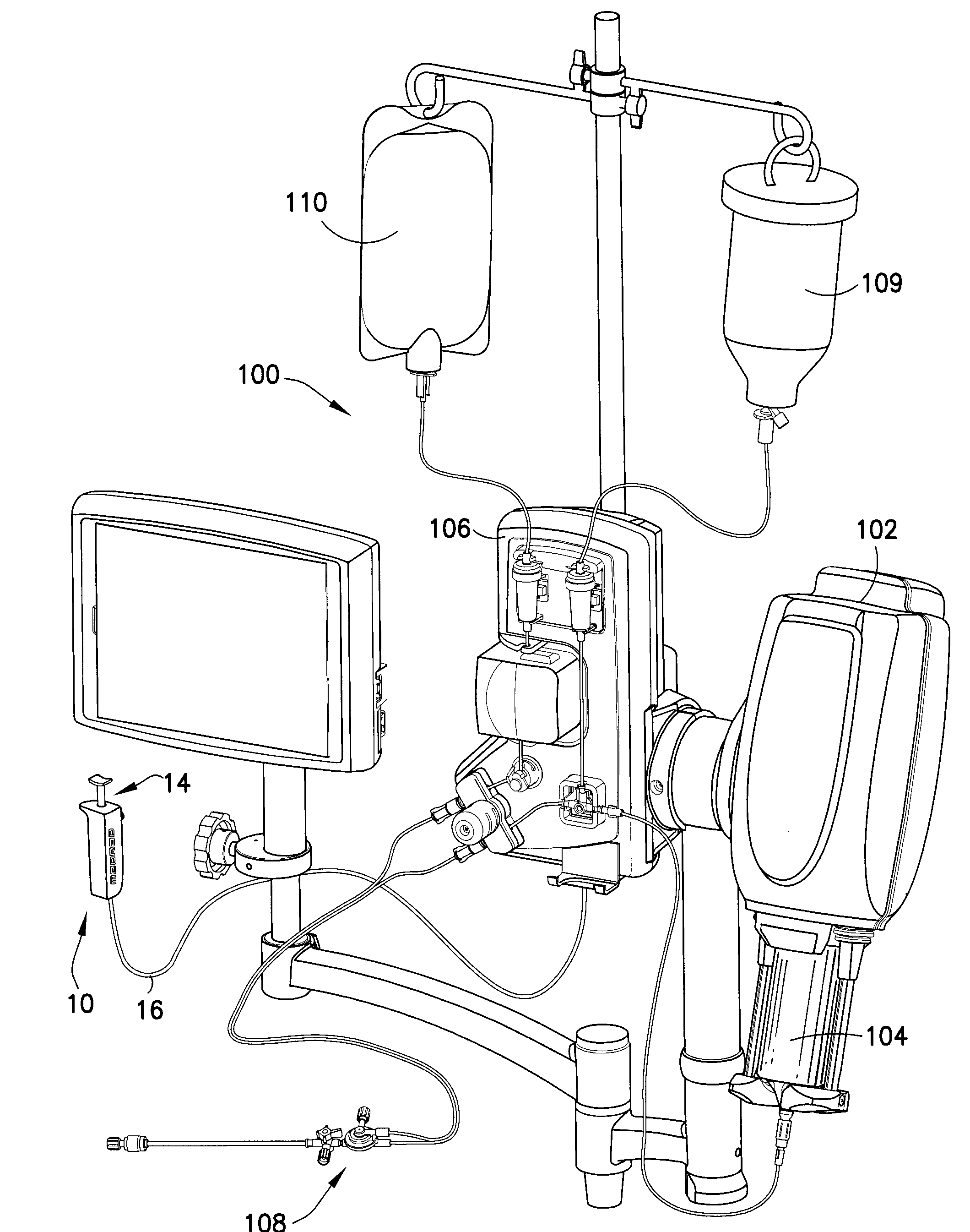
[0017]Additionally, the control device is generally adapted to control the delivery of additional injection fluids beyond contrast media. For example, it is common to supply saline to the patient during certain aspects of injection procedures, such as angiography. The control device is further adapted to start and stop the flow of an additional fluid, such as saline, to the patient when commanded by the user. If desired, the con...

Problems solved by technology

However, some known “mixing” solutions are somewhat low tech.
Prior art hand control devices in the market today do not provide such a mixing capability.
Further, futu...

Method used


Image

  • Fluid mixing control device for a multi-fluid delivery system
  • Fluid mixing control device for a multi-fluid delivery system
  • Fluid mixing control device for a multi-fluid delivery system

Examples


second embodiment

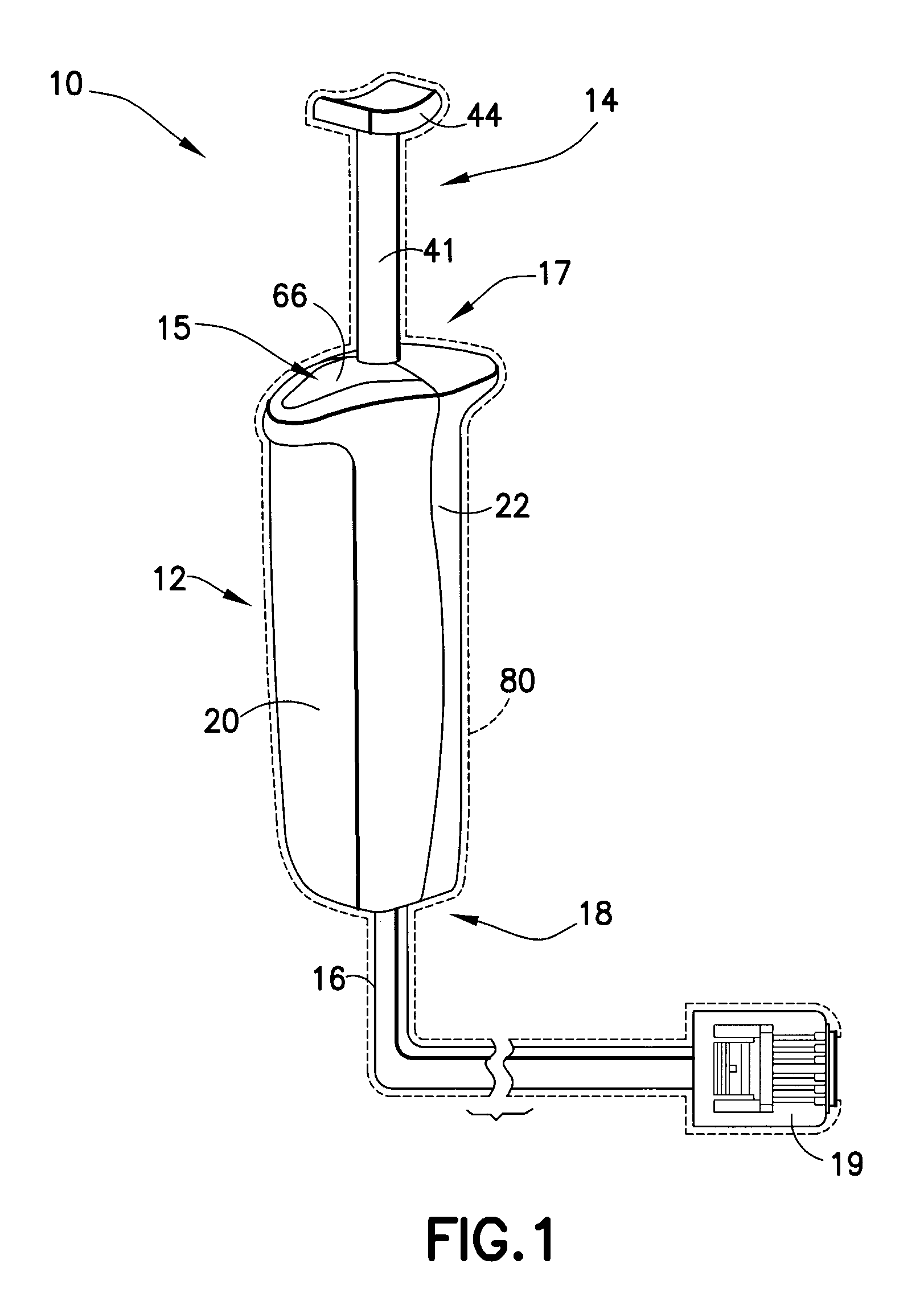
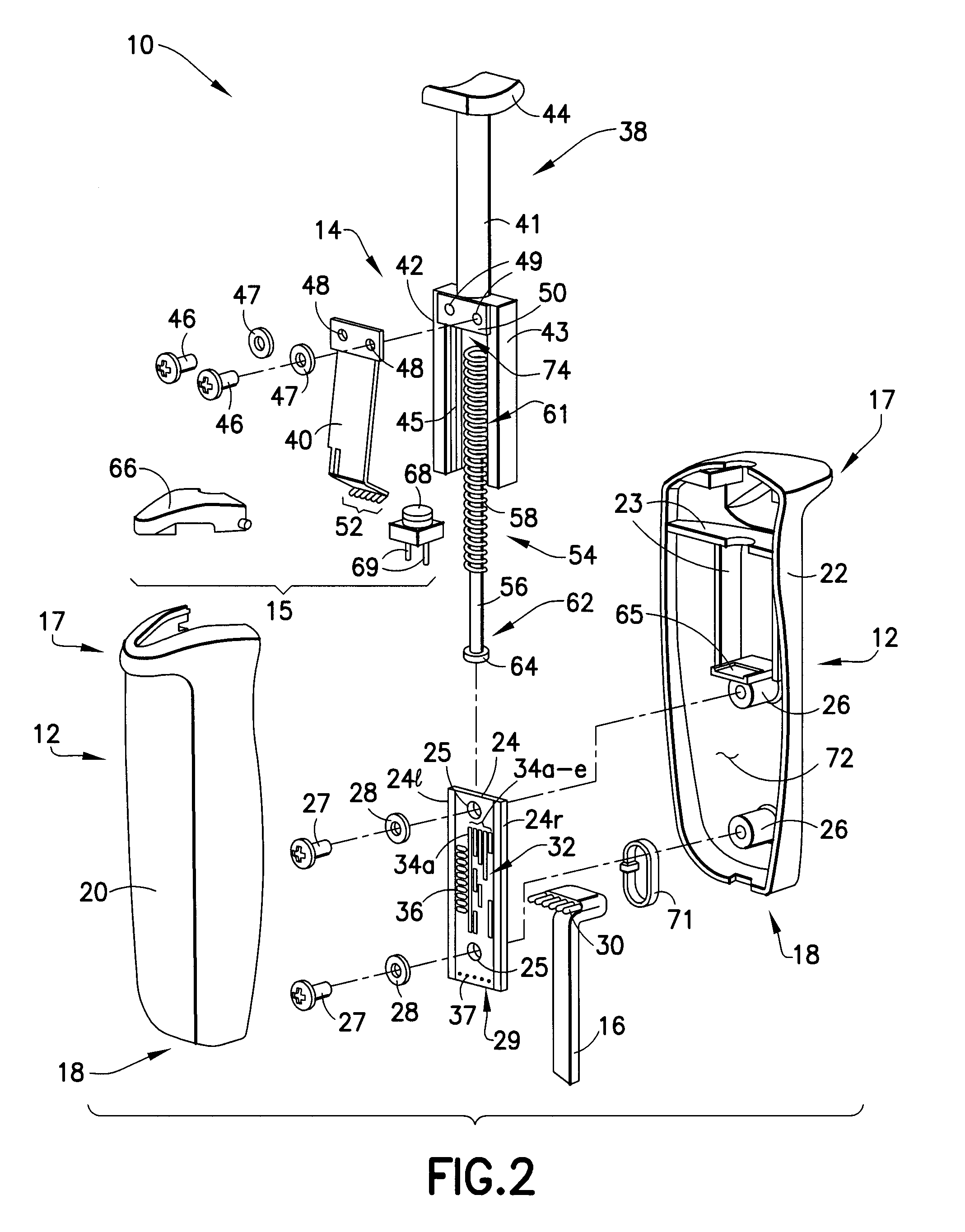
[0103]An alternative, second embodiment of the hand controller 10a is shown in FIGS. 5-9. The hand controller 10a is substantially functionally identical to the foregoing embodiment of the hand controller 10. The housing 12a of the hand controller 10a has the same external appearance as the housing 12 of the foregoing embodiment of the hand controller 10, and includes housing sides or portions 20a, 22a. The housing 12a is constructed of similar materials as the housing 12 in the foregoing embodiment. When the housing portions 20a, 22a are joined to enclose the internal components of the hand controller 10a, the visible components of the hand controller 10a, including the actuating member 38a, finger pad 44a, control button 66a, and cable 16a have generally the same external appearance as the forgoing embodiment of the hand controller 10. The internal components of the hand controller 10a have a slightly different configuration and arrangement from the foregoing embodiment of the han...

first embodiment

[0106]The electronic substrate 24a of the hand controller 10a is analogous in construction and operation to the electronic substrate 24 of the hand controller 10. Thus, the electronic substrate 24a includes the same conductive pattern 32a and wire holes 29a as found on the electronic substrate 24. However, unlike the previous electronic substrate 24, the current electronic substrate 24a lacks the sound producing structures 36. Additionally, the holes 25a defined in the electronic substrate 24a are now adapted to accept the posts 204 extending from housing portion 22a of the housing 12a to mount the electronic substrate 24a in position within housing portion 22a and within the housing 12a generally. The hand controller 10a also uses an analogous electrical connection between the control button 66a and the electronic substrate 24a. As with the control button 66 discussed previously, the control button 66a is adapted for a pivotal association with the housing 12a. However, the control ...


PUM


Abstract

The control device is used to control delivery of fluids from a multi-fluid delivery system during a medical injection procedure. The fluid delivery system includes an injector used to deliver injection fluids to a patient. The control device is operatively associated with the injector for controlling discrete flow rates of injection fluids delivered to the patient. The control device includes a housing, first and second actuators associated with the housing, and an electronic substrate disposed within the housing and having a conductive pattern. The first actuator is operatively associated with the conductive pattern. The conductive pattern includes a plurality of predetermined digital values corresponding to discrete flow rates of injection fluids to be delivered by the injector. The second actuator is operatively associated with the electronic substrate and initiates output signals to the injector corresponding to desired mixture ratios of the injection fluids to be delivered by the injector.

Description

RELATED APPLICATIONS[0001]The present application incorporates by reference U.S. patent application Ser. No. 11 / 085,616, filed Mar. 21, 2005 (published as U.S. 2005 / 0273056), and U.S. patent application Ser. No. 11 / 928,021, filed Oct. 30, 2007, the disclosures of which are incorporated herein by reference in their entirety.BACKGROUND OF THE INVENTION[0002]1. Field of the Invention[0003]The present invention relates generally to control devices for controlling operation of fluid-supplying machines or apparatus used in medical procedures such as angiography and, further, to hand-held control devices for controlling the flow rate of fluids, such as contrast media and / or common flushing agents, injected into a patient during medical procedures, such as angiography.[0004]2. Description of Related Art[0005]Angiography is a procedure used in the detection and treatment of abnormalities or restrictions in blood vessels. During angiography, a radiographic image of a vascular structure (i.e.,...

Claims


Application Information

Patent Timeline
IPC IPC(8): A61M5/00A61M1/00G05D7/06
CPCA61M5/1407A61M5/16827A61M2205/502G05D7/0676G05D11/005A61M5/007A61M5/31546A61M5/31548A61M2005/1787A61M2205/18G05D11/003A61B6/481A61M5/16877G05D11/02A61M2205/50
Inventor SCHRIVER, RALPH H.JOYCE, THOMAS P.RILEY, MICHEALBARLOW, WILLIAM D.
Owner BAYER HEALTHCARE LLC
Why Eureka
Try Eureka