Low cost electronic compass with 2d magnetometer

Inactive Publication Date: 2010-05-13
BREAKWATERS INNOVATIONS
View PDF14 Cites 2 Cited by
  • Summary
  • Abstract
  • Description
  • Claims
  • Application Information

AI Technical Summary

Benefits of technology

[0004]Accordingly, the inventors propose an electronic device comprising an orientation sensor with a two-dimensional magnetometer. The sensor is operative to supply a first signal and a second signal for determining first and second components, respectively, of the three-dimensional earth-magnetic field vector at a geographic location of the device. The device has first means for determining multiple candidates for the third component of the earth-magnetic field vector based on the first and second components and on a given strength of the earth-magnetic field at the geographic location of the device. The device has second means for determining multiple further candidates for the gravity vector, based on a given inclination and a given strength of the earth-magnetic field vector at the geographic location of the device, assuming that an axis of the device is being held horizontally. The device has third means for selecting a relevant one of multiple candidates for the third component of the earth-magnetic field vector and for selecting a further relevant one of the multiple further candidates for the gravity vector.
[0005]The invention is based on the following assumptions: the values are known of the magnitude and inclination of the earth-magnetic field at the location of the device; at least one of the body axes of the device is being held horizontally in operational use of the device. Based on these assumptions, an educated guess can be made about the actual orientation of the device (and about derivative quantities, such as heading and tilt angles) with respect to the earth.

Problems solved by technology

Although this represents a restriction, its impact is low in operational use.

Method used


Image

  • Low cost electronic compass with 2d magnetometer
  • Low cost electronic compass with 2d magnetometer
  • Low cost electronic compass with 2d magnetometer

Examples


Embodiment Construction

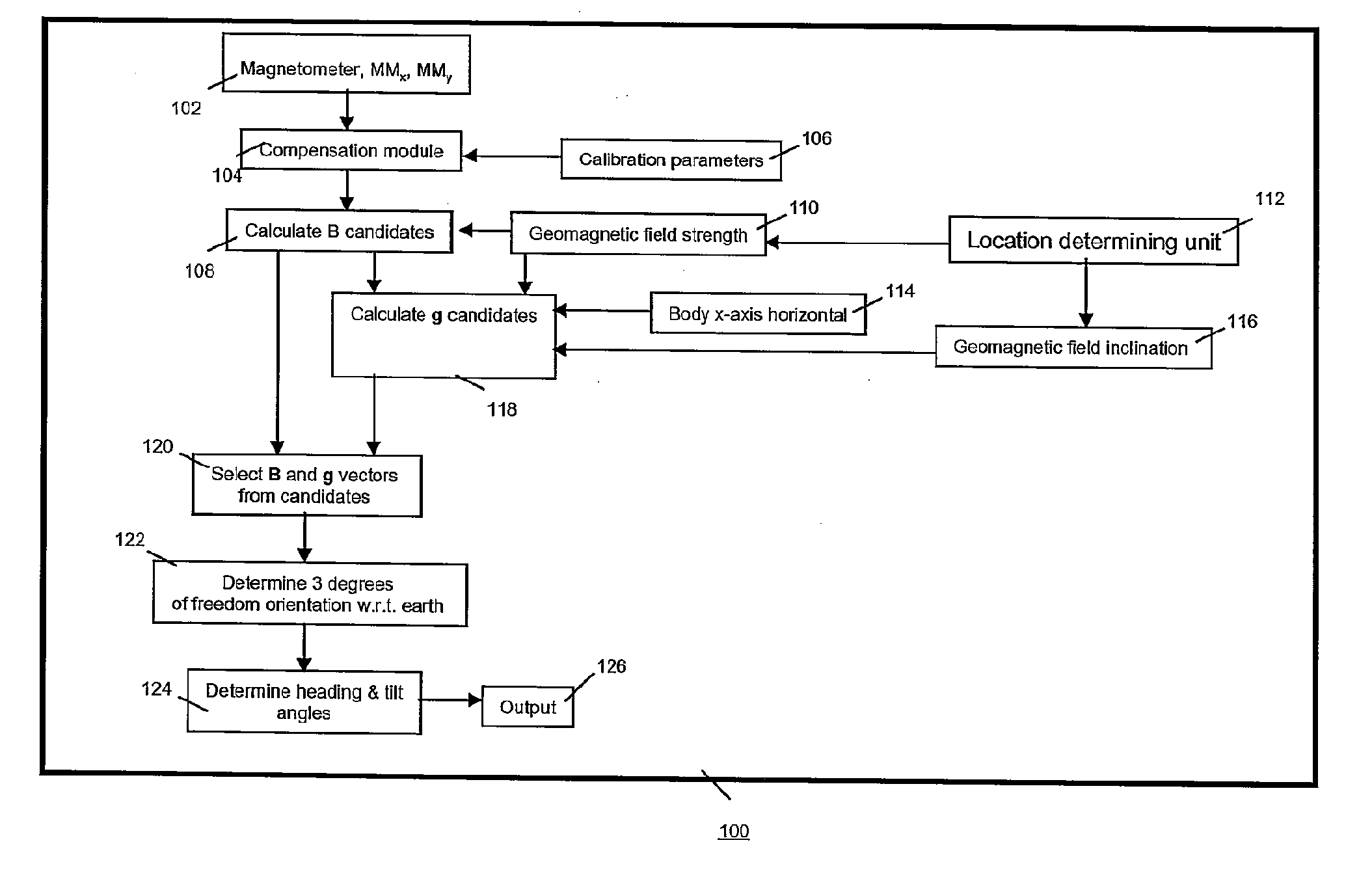
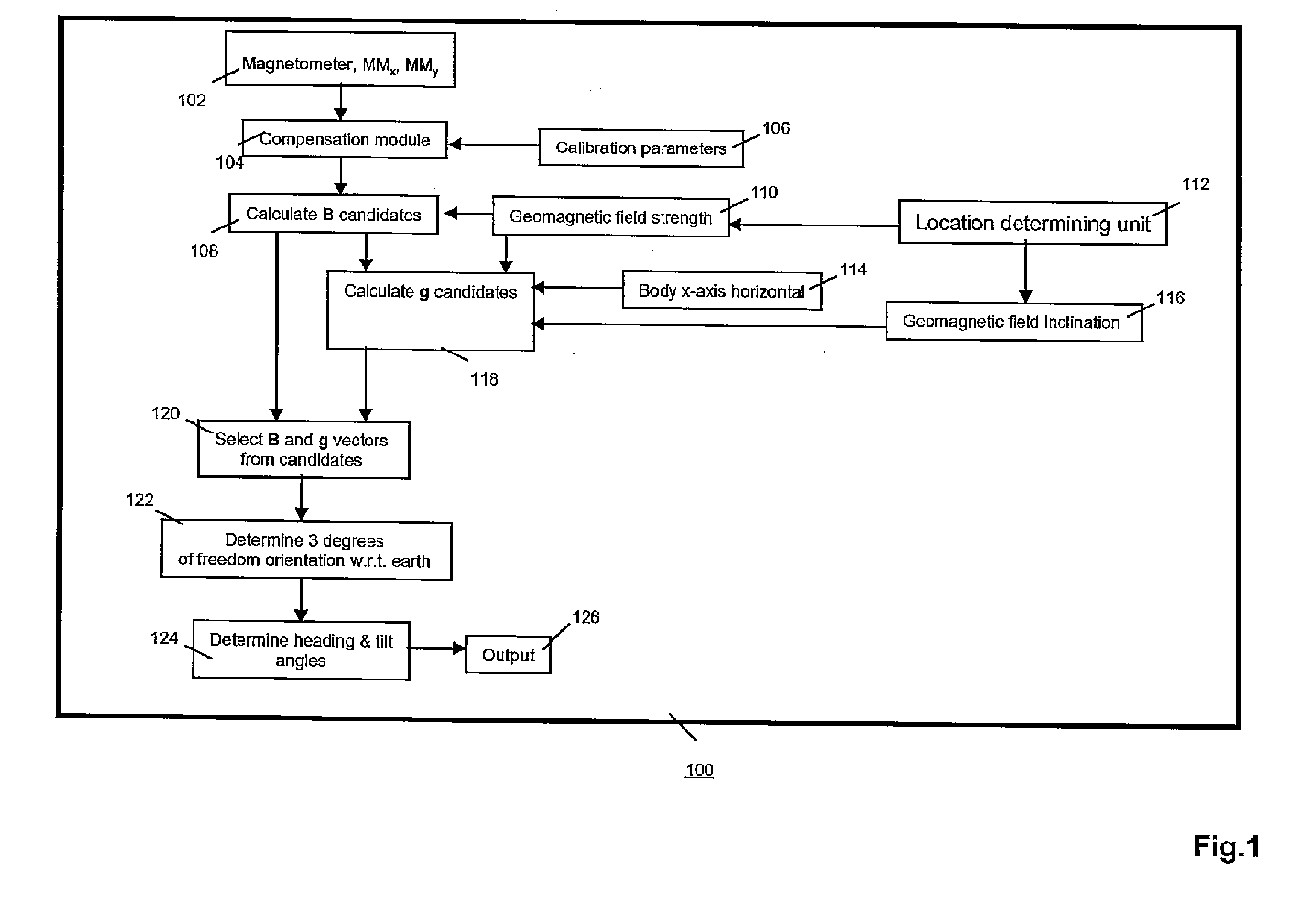
[0019]FIG. 1 is a functionality diagram of an electronic device 100 in the invention. Device 100 comprises a 2D magnetometer 102 that supplies signals MMx and MMy. From these signals, two of the three orthogonal components are determined that specify the earth-magnetic field vector at the geographic location of device 100 with respect to a coordinate system fixed to device 100. This coordinate system has an x-axis, a y-axis perpendicular to the x-axis, and a z-axis perpendicular to both the x-axis and the y-axis. The components of the earth-magnetic field in the directions of the x-axis and y-axis, are referred to here as BX and By, respectively. Device 100 has a compensation module 104 for compensating signals MMX and MMy for, e.g., offsets, sensitivity, misalignment, etc. The output of compensation module 104 is representative of the components of the earth-magnetic field vector B along two orthogonal directions in the coordinate system of device 100. Compensation module 104 recei...


PUM


Abstract

An electronic compass has a 2D magnetometer for determining two of the three components of the earth-magnetic field vector. Values for the magnitude and inclination of the field at the location of the device are given. If at least one of the body axes of the device is held horizontally in operational use, an educated guess can be made about the actual orientation of the device (e.g., heading and tilt angles) with respect to the earth. Accordingly, this compass is a very-low cost device.

Description

FIELD OF THE INVENTION[0001]The invention relates to an electronic device comprising an orientation sensor with a two-dimensional magnetometer.BACKGROUND ART[0002]U.S. Pat. No. 6,836,971 discloses a tilt-compensated electronic compass. Its operation is based on calculating, rather than on measuring, the earth's magnetic field component Z in a direction orthogonal to the two measurement axes of a 2-axis magnetic sensor. The orthogonal component Z can be calculated using a stored value for the earth's magnetic field strength applicable over a wide geographic region. The calculation also requires using measured field values from the 2-axis sensor. Once Z is known, and using input from a 2-axis tilt sensor, the compensated orthogonal components X and Y can be calculated by mathematically rotating the measured field strength values from a tilted 2-axis sensor back to the local horizontal plane.SUMMARY OF THE INVENTION[0003]The invention relates to an orientation sensor and tilt-compensat...

Claims


Application Information

Patent Timeline
IPC IPC(8): G01C17/30G01C21/00
CPCG01C17/00G01C21/00G01C17/30
Inventor BOEVE, HANS MARC BERTIKKINK, TEUNIS JANDURC, HARIS
Owner BREAKWATERS INNOVATIONS
Why Eureka
Try Eureka