Control device and method for influencing the engine speed and the degree of slip of a clutch of a ship drive system

Inactive Publication Date: 2009-12-03
ROBERT BOSCH GMBH
View PDF0 Cites 2 Cited by
  • Summary
  • Abstract
  • Description
  • Claims
  • Application Information

AI Technical Summary

Benefits of technology

[0007]It is therefore the object of the present invention to create a control device for a ship drive system that ensures, in technically simple fashion, a clutch engagement operation having low impact on the drive system, in particular for a high-output engine system.
[0010]The advantage of the solution according to the present invention is in particular that with it, smooth clutch engagement is achieved in simple fashion in terms of signal processing engineering, especially when changing the direction of travel. This is because control is not applied to the clutch by the discontinuity in control output, but instead the control output changes gradually in the direction of the desired clutch slip. The full output of the ship drive system is not thereby limited, but the clutch engagement operation is merely carried out with low impact on the drive system. In addition, thanks to the slower acceleration resulting from the ramp function characteristic curve the ship's master has more time to establish the desired maneuvering speed before the clutch must again be released. This makes maneuvering simpler and also safer. The adjustable-slip clutch transfers no torque at maximum slip, and the clutch engages at very low slip. This range characterizes the clutch slip “s”. The clutch engagement time span “t” for smooth clutch engagement is preferably in the range of a few seconds, very preferably in the range from 1 to 2 seconds. For larger ships having a greater inertia to be moved, and for ships with less excess power output, it is proposed to select a shorter clutch engagement time span “t”.
[0011]According to a feature that improves the invention, it is proposed that the electronic control unit split the control instruction predefined by the manual command transducer, i.e. delivers it simultaneously to a first converter unit for characteristic-curve-controlled determination of an engine speed signal for the downstream engine, and also to a second converter unit for characteristic-curve-controlled determination of a rotation direction signal for the downstream clutch. The slip definition unit that is a subject of the invention can be placed downstream from the second converter unit in order to perform its function for clutch control application. The slip definition unit is thereby optimally placed along the signal flow in order to perform its desired function of smooth clutch engagement.

Problems solved by technology

The sensor means necessary for the regulation of clutch operation result in considerable electronic complexity.
This results in a high mechanical load on the drive train, especially when maneuvering.

Method used


Image

  • Control device and method for influencing the engine speed and the degree of slip of a clutch of a ship drive system
  • Control device and method for influencing the engine speed and the degree of slip of a clutch of a ship drive system

Examples


Embodiment Construction

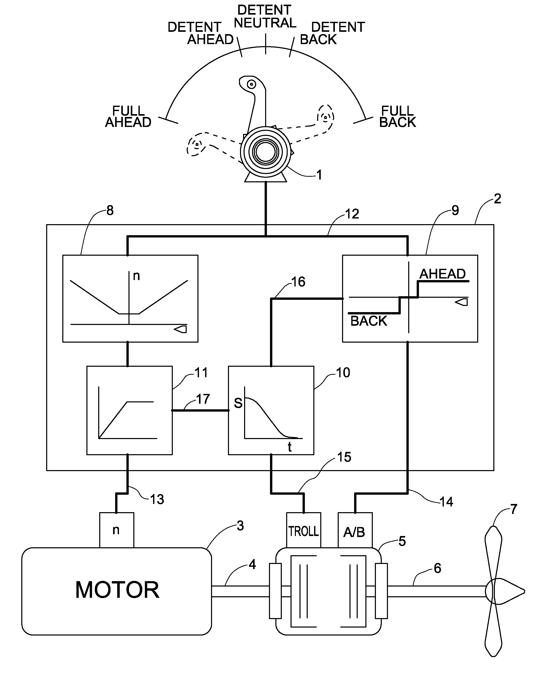
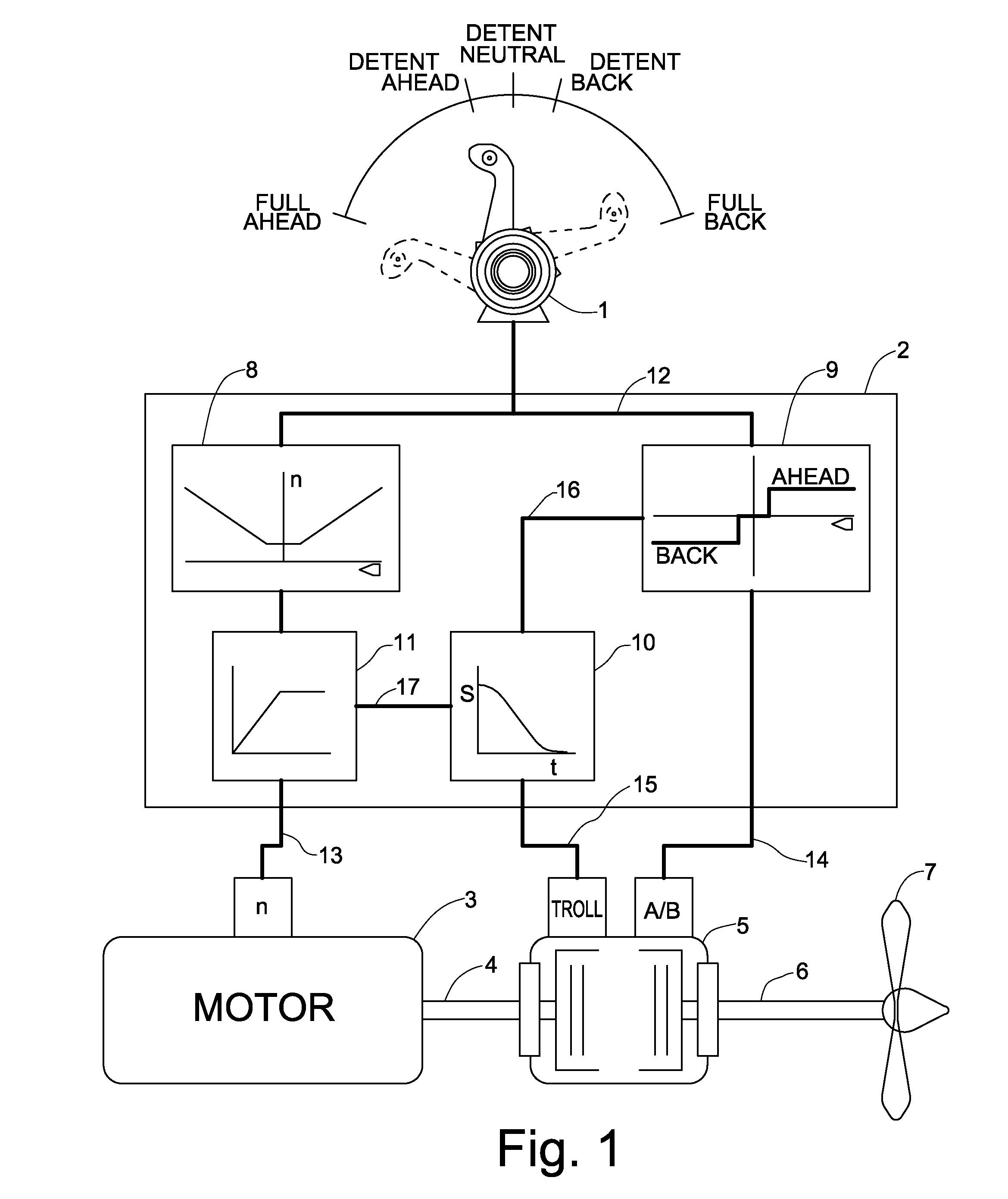
[0015]According to the Figure, the control device encompasses a command transducer 1 for manually selecting the rotation direction and the travel speed of the ship (not further depicted here) as a function of the operating lever position selected by the ship's master. The control signal thereby generated goes to an electronic control unit 2 that performs a special signal processing action (described in further detail below) in order to establish at the output side the rotation speed “n” of an engine 3, as well as a degree of slip of an adjustable clutch integrated into a downstream transmission 5, and the rotation direction of transmission 5. Engine 3 is a combustion engine and is connected via a drive shaft 4 to the input of transmission 5. On the output side of transmission 5, a propeller shaft 6 extends to a propeller 7 for the purpose of driving the ship.

[0016]Electronic control 2 splits up, on the input side, the operating instruction predefined by manual command transducer 1 b...


PUM


Abstract

A control device and method for influencing the rotation speed of an engine (3) and the degree of slip of a clutch, downstream therefrom, of a transmission (5) of a ship drive system, by way of an electronic control unit (2) in accordance with a manual command transducer (1) for selecting the rotation direction and travel speed, wherein upon engagement of the clutch in order to initiate travel ahead or back, a slip definition unit (10) of the electronic control unit (2) influences the degree of slip of the clutch in accordance with a ramp function characteristic curve, in order to decrease clutch slip (s) during a defined clutch engagement time span (t).

Description

CROSS REFERENCE TO RELATED APPLICATIONS[0001]This application claims priority of German patent application no. 10 2008 025 480.0 filed May 27, 2008, which is incorporated by reference herein.FIELD OF THE INVENTION[0002]The present invention relates to a control device and a method for influencing the rotation speed of an engine, and the degree of slip of a clutch downstream therefrom, of a ship drive system, by way of an electronic control unit in accordance with a manual command transducer for selecting the rotation direction and travel speed.BACKGROUND OF THE INVENTION[0003]The area of application of the present invention extends to ship drive systems, preferably for the yacht-building sector. Ship drive systems driven by combustion engines and preferably having one or two marine propellers are usually utilized here. A rotary motion is imparted to the propellers via a transmission downstream from the engine. While the engine is usually controllable in terms of its rotation speed i...

Claims


Application Information

Patent Timeline
IPC IPC(8): G06F19/00
CPCB63H23/30F16D2500/1105B63H2023/0291
Inventor HENKNER, RAINER
Owner ROBERT BOSCH GMBH
Why Eureka
Try Eureka