Screw Driver With A Variable Handle

Inactive Publication Date: 2010-05-13
HUNG KUN CHIH
View PDF14 Cites 14 Cited by
  • Summary
  • Abstract
  • Description
  • Claims
  • Application Information

AI Technical Summary

Benefits of technology

[0009]An objective of the invention is to provide a screw driver with a variable

Problems solved by technology

However, one usually has to impose a larger torque when fastening or loosening a screw.
Such a straight-bar screw driver is difficult to use in such situations because the driving direction of the working head is the same as that of the straight bar.
However, even

Method used


Image

  • Screw Driver With A Variable Handle
  • Screw Driver With A Variable Handle
  • Screw Driver With A Variable Handle

Examples


Example

[0021]The present invention will be apparent from the following detailed description, which proceeds with reference to the accompanying drawings, wherein the same references relate to the same elements.

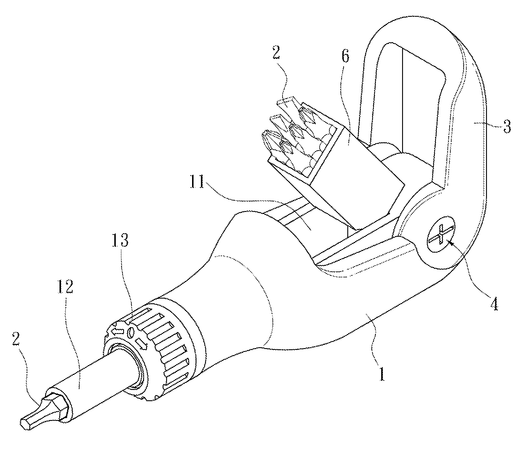
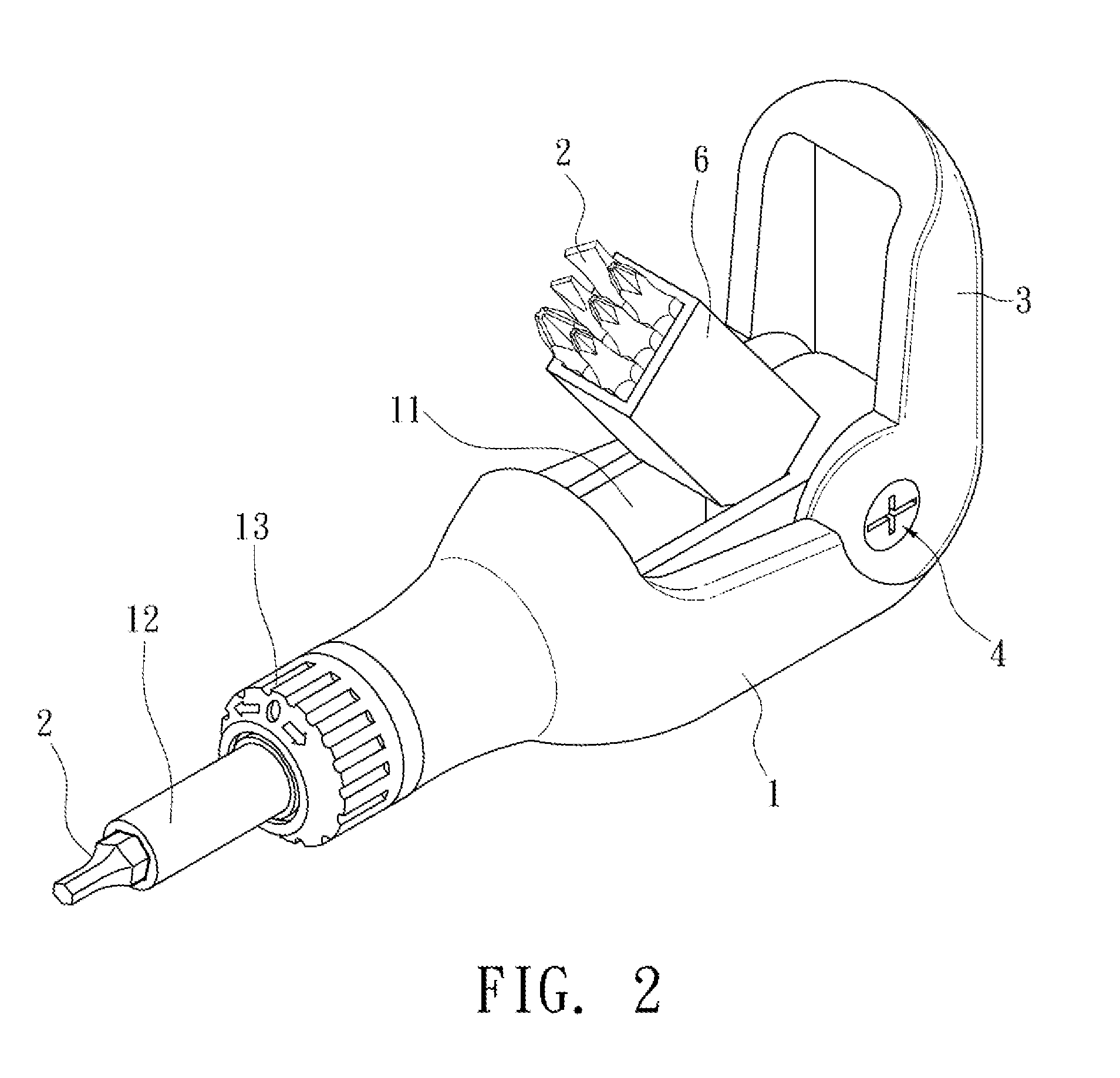
[0022]An embodiment of the disclosed screw driver with a variable handle includes: a body 1, at least one friction ring 5, and an accommodating box 6.

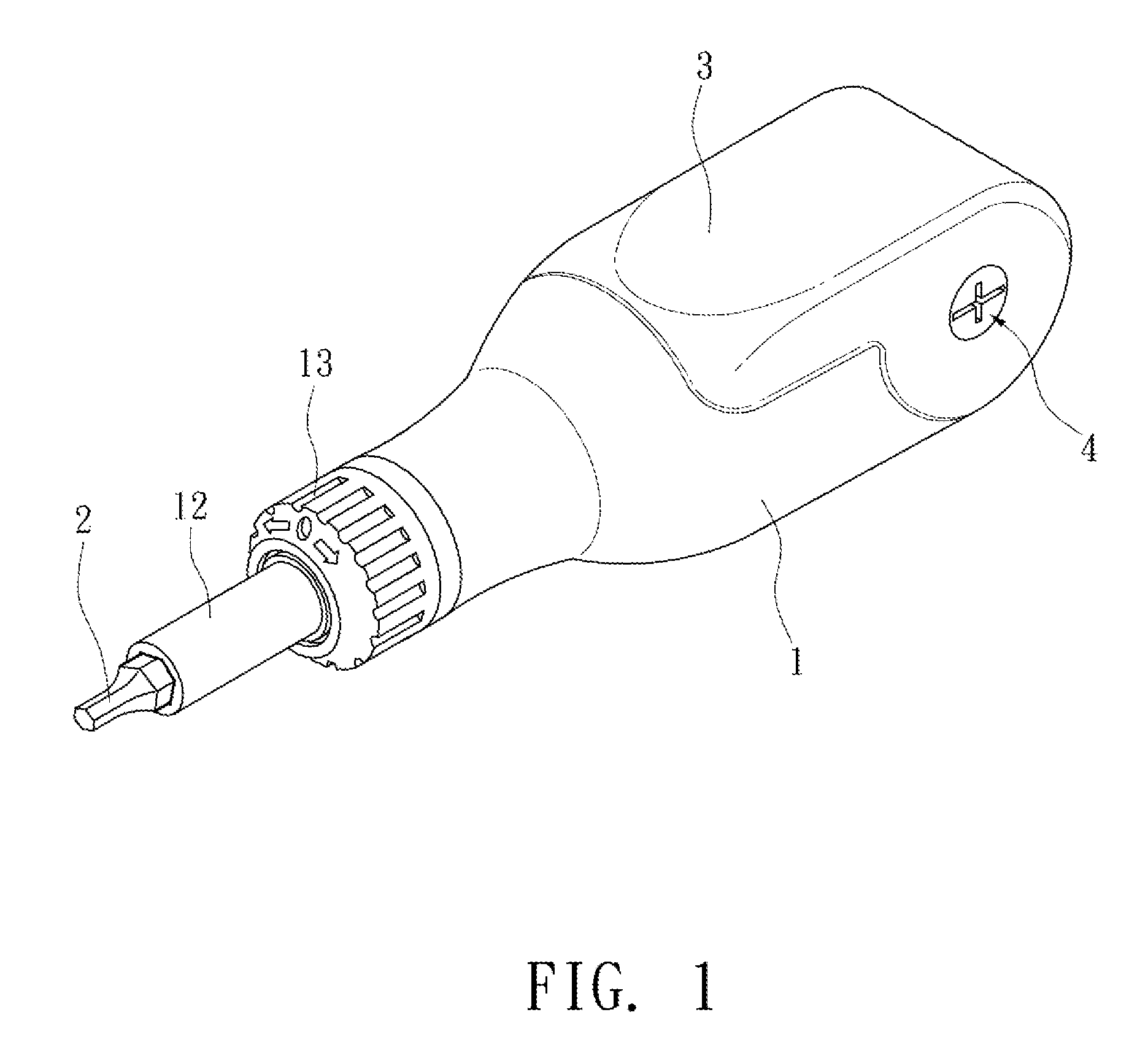
[0023]The body 1 has an accommodating room 11 between its two ends. One end of the body 1 is provided with a mounting part 12 for a working head 2 to mount thereon. In this embodiment, a ratchet mechanism 13 is installed between the mounting part 12 and the body 1.

[0024]The other end of the body 1 is pivotally installed with an auxiliary handle 3 to cover the accommodating room 11. In this embodiment, the body 1 has two first through holes 14 on the end of the auxiliary handle 3. The auxiliary handle 3 has a second through hole 31 on the end corresponding to the body 1. The second through hole 31 and the two first through holes 14 are in...


PUM


Abstract

A screw driver with a variable handle has a body. One end of the body has a mounting part, and the other end is pivotally installed with an auxiliary handle. The body has an accommodating room for accommodating an accommodating box. The auxiliary handle covers the accommodating room when storing the screw driver. It is flipped open for holding when the screw driver is in use.

Description

BACKGROUND OF THE INVENTION[0001]1. Field of Invention[0002]The invention relates to a screw driver with a variable handle and, in particular, to a screw driver with a collapsible auxiliary handle.[0003]2. Related Art[0004]The conventional screw driver is usually a simple straight bar with a working head on its one end. The rod has a handle for the user to hold and turn, with the working head driving an object such as a screw. However, one usually has to impose a larger torque when fastening or loosening a screw. Such a straight-bar screw driver is difficult to use in such situations because the driving direction of the working head is the same as that of the straight bar.[0005]FIG. 6 shows a conventional Allen wrench, which is different from the usual screw driver. As shown in the drawing, it has a straight bar 90 with a working head 91 on its one end. The other end is mounted with a handle 92 to render a T shape. Therefore, the user can hold the T-shaped handle 92 to easily exert ...

Claims


Application Information

Patent Timeline
IPC IPC(8): B25G1/08
CPCB25G1/085
Inventor HUNG, KUN-CHIH
Owner HUNG KUN CHIH
Why Eureka
Try Eureka