Modular latch

a module and latch technology, applied in the field of automotive door latches, can solve the problems of increasing complexity, inability to meet the needs of users, and inability to achieve the desired effect,

Active Publication Date: 2010-05-13
MAGNA CLOSURES INC
View PDF38 Cites 40 Cited by
  • Summary
  • Abstract
  • Description
  • Claims
  • Application Information

AI Technical Summary

Benefits of technology

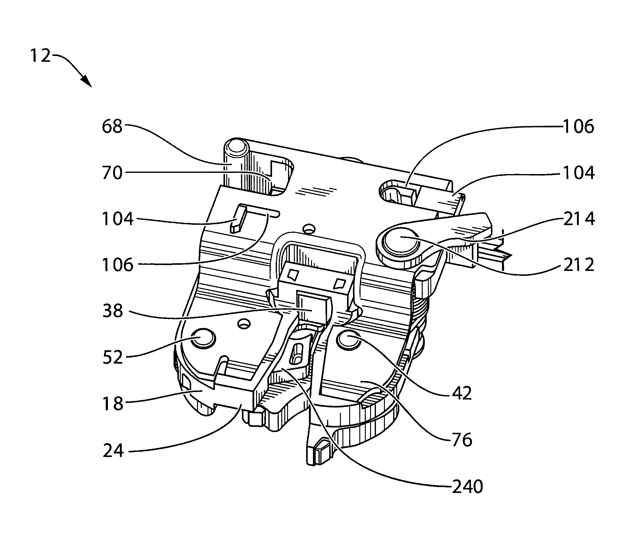
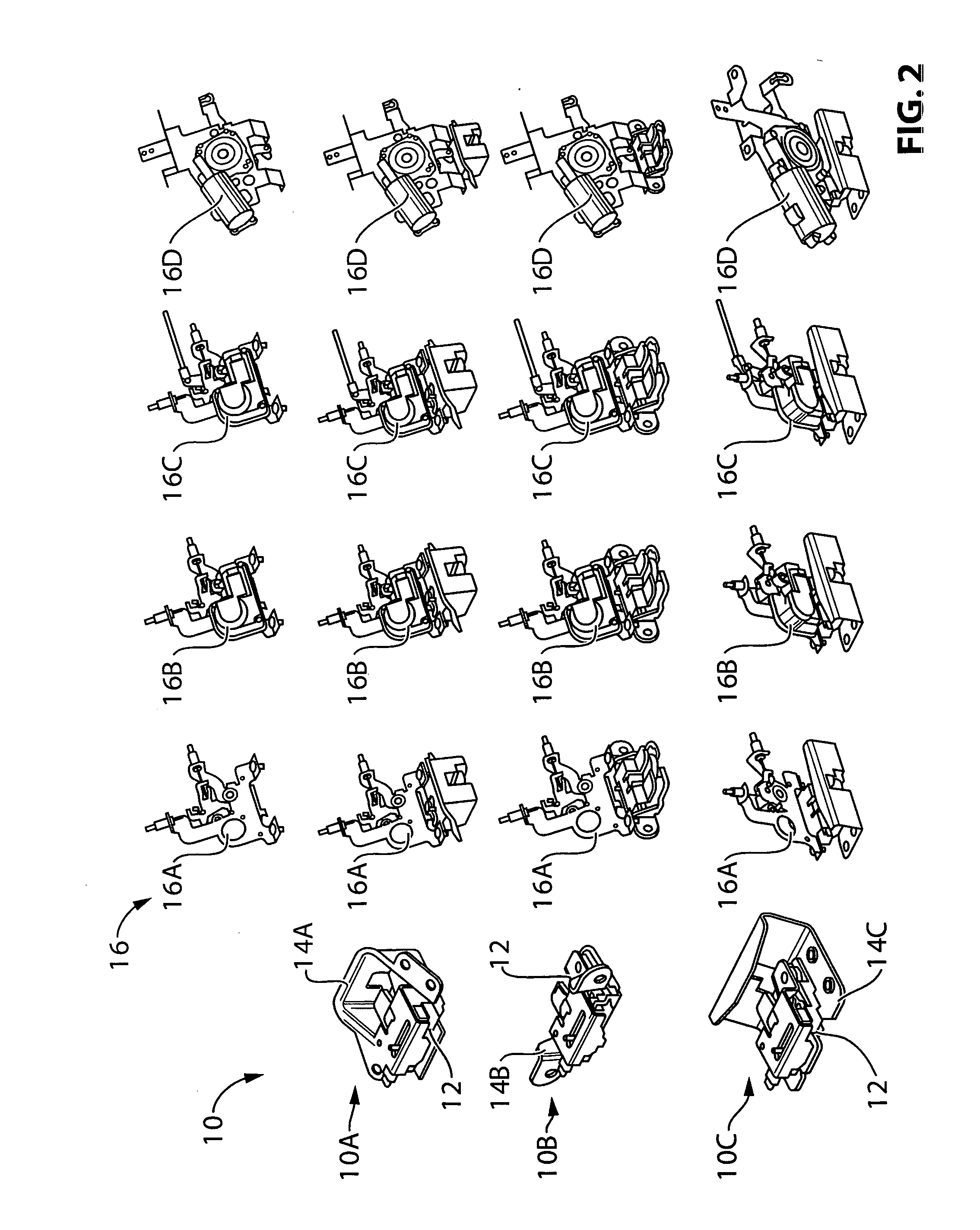
[0007]In an aspect of the invention there is a modular latch for an automotive vehicle. It has a latch core. The latch core has a housing and a ratchet and pawl rotatably mounted to the housing. The ratchet and pawl are cooperatively operable to move between an engaged position to hold a striker and a released position. The latch core is operable to be secured to one of a plurality of mounting plates to secure and present the latch core to the striker. The plurality of mounting plates may include (a) a mounting plate for a lift gate latch, (b) a mounting plate for a decklid latch, and (c) a mounting plate for a sliding door latch. The latch core is further operable to mount any one of a plurality of latch modules, including a manual release latch module, a power release latch module, a power lock and unlock latch module, and a power cinching and release latch module.

Problems solved by technology

Additionally, in a vehicle collision, there is the potential that sudden deceleration may generate an inertial load on either the ratchet or pawl to accidentally release the latch.
This may not be desirable.
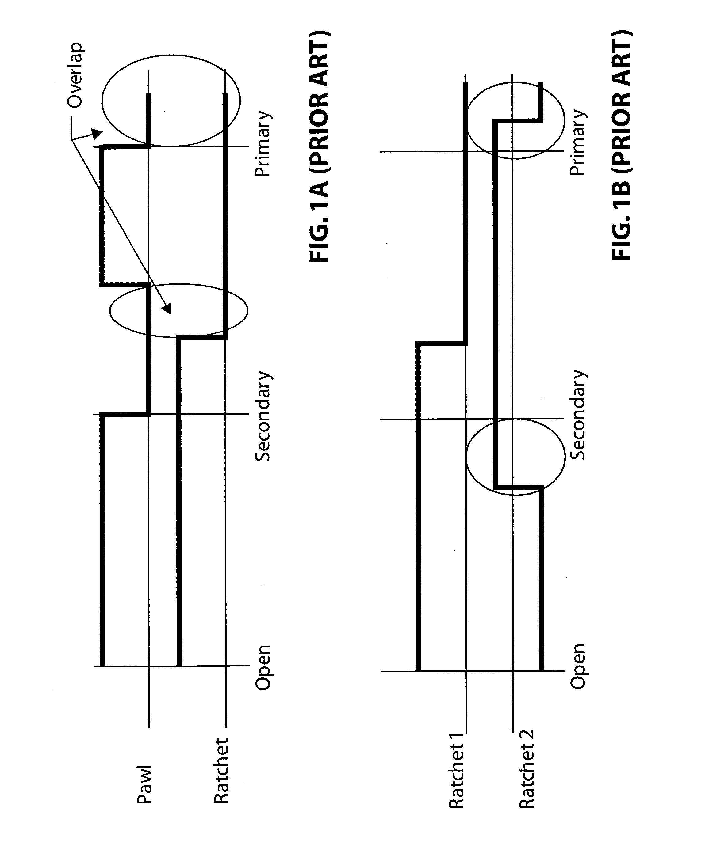
One problem with this switch strategy is that the switches report the same state (OFF and OFF) when the ratchet is in the primary engagement position, and an interlude between the primary and secondary engagement positions.
The controller is forced to use additional intelligence to provide the desired cinching effect, resulting in increased complexity and more expensive components.
This results in the motor continuing to cinch briefly, but disquietingly, after the latch is fully closed in the primary engagement position.

Method used


Image

  • Modular latch
  • Modular latch
  • Modular latch

Examples


Embodiment Construction

[0086]The description that follows and the embodiments described therein are provided by way of illustration of an example, or examples, of particular embodiments of the principles, aspects or features of the present invention. These examples are provided for the purposes of explanation, and not of limitation, of those principles and of the invention. In the description, like parts are marked throughout the specification and the drawings with the same respective reference numerals. The drawings are generally to scale unless noted otherwise, although the scale may differ from drawing to drawing. Reference to directions such as up and down, front and back, left and right, top and bottom, may tend to be arbitrary, and these terms may be used for convenience rather than to define a required orientation, unless noted otherwise. The terminology used in this specification is thought to be consistent with the customary and ordinary meanings of those terms as they would be understood by a pe...


PUM


Abstract

A modular latch for an automotive vehicle is provided. It includes a latch core (a housing and a ratchet and pawl rotatably mounted to the housing), a mounting plate that secures the latch core to the vehicle. The latch cure can use any of a plurality of different mounting plates for a lift gate latch, a decklid latch, and a sliding door latch; A latch module is mounted to the latch core to provide different functional including a manual release latch module, a power release latch module, a power lock and unlock latch module, and a power cinching and release latch module. The latch cure may fit a more or less universal envelope. The latch may employ one or more status sensors. Those status sensors may sense striker position, and may not necessarily include any sensors mounted to monitor ratchet position. The latch may include a layered latch core in which one or more sensor members move in different planes from the pawl and ratchet.

Description

FIELD OF THE INVENTION[0001]The present invention relates to automotive door latches, such as may be used in such things as lift gates, deck lids, or sliding doors.BACKGROUND OF THE INVENTION[0002]Latch designs need to accommodate different packaging requirements for lift gates, decklids and sliding doors. In addition, automotive companies are looking to provide new features for their vehicles, even on components such as latches. Features such as power locking, power releasing and power cinching are rapidly becoming popular. Other manufacturers desire simpler and less expensive locks. The need for multiple latch packages and feature sets results in the need for multiple latch designs while manufacturers are looking to standardize parts in order to reduce assembly costs. Therefore, it may be desirable to produce a modular latch that can accommodate different features within one assembly.[0003]Additionally, in a vehicle collision, there is the potential that sudden deceleration may ge...

Claims


Application Information

Patent Timeline
Patent Type & Authority Applications(United States)
IPC IPC(8): E05C3/16E05C3/06
CPCE05B63/0056E05B77/06E05B81/06E05B81/14E05B81/20E05B81/36E05B81/64E05B81/68E05B81/90E05B85/02E05B85/26E05B81/15Y10T292/1047Y10T292/1082E05B83/18E05B85/20
Inventor MITCHELL, SCOTT J. R.PLAYIA, JAGDEEPLIANG, CHUANANDROAS, DANIGHORGHORIAN, DIKRANNEYMAN, ILYAILEA, IOAN D.ZEABARI, JOHN G.VASILESCU, EDUARD
Owner MAGNA CLOSURES INC
Why Eureka
Try Eureka