Mode selection technique for a laser

Active Publication Date: 2010-05-13
LUXINAR LTD
View PDF7 Cites 10 Cited by
  • Summary
  • Abstract
  • Description
  • Claims
  • Application Information

AI Technical Summary

Benefits of technology

[0015]The recess may be in the form of a slot, circular hole or other shape that acts to produce lowest order waveguide mode selection within the confines of the discharge region, by creating an internal

Problems solved by technology

No further measures were taken to improve the mode quality from the device.
They considered that the 2 mm restriction was required to generate the fundamental mode in the volume of the narrow, waveguide, axis and consequently, this restriction to the volume of the laser active region reduced the output power that could be obtained.
A major disadvantage to this design is that the electrodes are difficult to manufacture as a curvatu

Method used


Image

  • Mode selection technique for a laser
  • Mode selection technique for a laser
  • Mode selection technique for a laser

Examples


Embodiment Construction

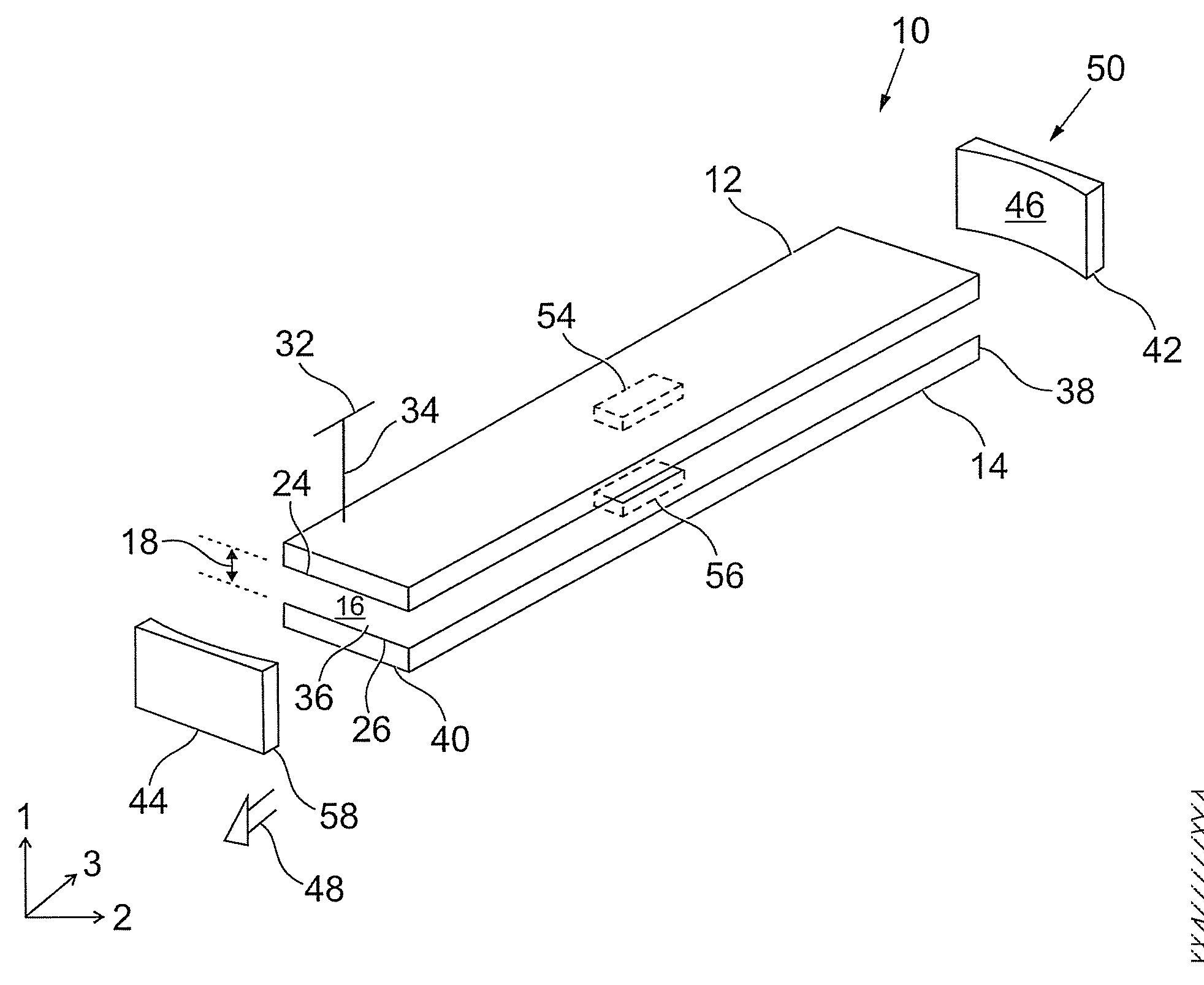
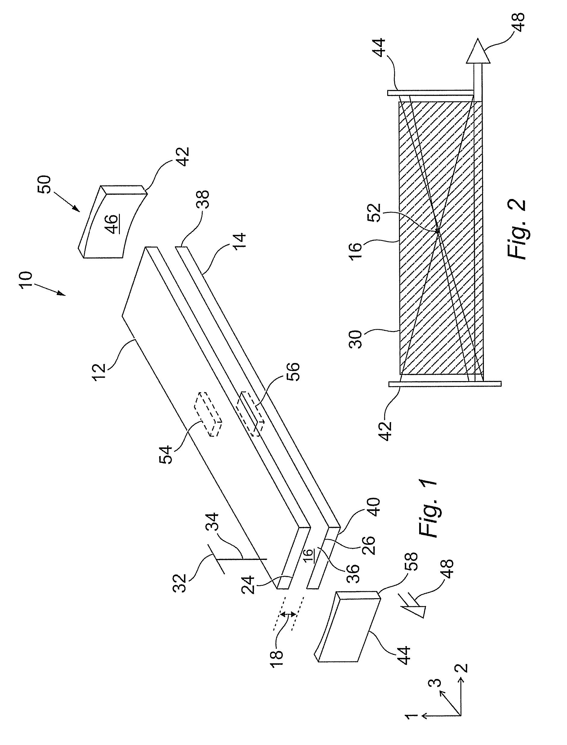
[0038]Reference is initially made to FIG. 1 of the drawings which illustrates a mode selective laser, generally indicated by reference numeral 10, according to an embodiment of the present invention. Laser 10 comprises a pair of elongated rectangular planar electrodes 12,14 formed from a conductive metal such as aluminium. The planar dimensions of electrodes 12,14 will determine the size of the discharge region 16, created there between, and consequently the output power of the laser 10. For a 100w laser in CO2 the electrodes could be around 480 mm in length and 45 mm wide. The electrodes 12,14 are typically adapted to include one or more coolant channels (not shown) through which water can flow.

[0039]The electrodes 12,14 are spaced apart by a waveguide height, or inter-electrode gap 18. Typically the gap 18 is 1 mm to 4 mm in height, with a height in the range 1.3 mm to 2.8 mm in a preferred embodiment. The electrodes 12,14 are held apart at the desired height 18.

[0040]The discharg...


PUM


Abstract

A mode selection technique in a laser is described wherein a recess is formed in a surface of a waveguide in the laser. The recess provides a region of free space propagation within the waveguide which preferentially selects the lowest order mode. A mode selective RF excited CO2 slab laser, having a stable resonator in the waveguide dimension and a negative branch unstable resonator in the non-waveguide dimension, is constructed and the position and size of the recess is considered to provide low order mode selection.

Description

[0001]The present invention relates to a mode selection technique in a laser and more particularly, though not exclusively, to an RF excited CO2 slab waveguide laser where a recess is located on a surface of the waveguide to provide a region of free space propagation within the waveguide. The position and size of the recess can be varied to provide mode selection.BACKGROUND OF THE INVENTION[0002]A typical RF excited CO2 slab waveguide laser is described in U.S. Pat. No. 5,123,028, assigned to Coherent, Inc., USA. A pair of rectangular planar electrodes having exposed light reflecting surfaces are spaced apart and dimensioned in a manner to guide light i.e. a waveguide, in a plane perpendicular to the reflecting surfaces. Light parallel to the reflecting surfaces is not constrained other than by resonator mirrors located at the ends of the electrodes. The resonator structure is designed as a negative branch unstable resonator in the non-waveguide dimensions. A stable resonator is use...

Claims


Application Information

Patent Timeline
IPC IPC(8): H01S3/098H01S3/03
CPCH01S3/038H01S3/041H01S3/063H01S3/0804H01S3/2232H01S3/08059H01S3/0818H01S3/0973H01S3/0805
Inventor MARKILLIE, GAVIN ALAN JAMESLEE, JASON ROBERT
Owner LUXINAR LTD
Why Eureka
Try Eureka